Thermally conductive sheet

A heat-conducting sheet and mesh technology, used in conductors, insulated conductors, semiconductor devices, etc., can solve the problems of wrinkles, elongation, and reduced operability, and achieve reduced surface area, high strength, and good operability. Effect

Active Publication Date: 2013-05-01
SEKISUI POLYMATECH CO LTD
View PDF8 Cites 10 Cited by
  • Summary
  • Abstract
  • Description
  • Claims
  • Application Information

AI Technical Summary

Problems solved by technology

However, if it is too thin, there may be problems such as elongation, cracking, and wrinkling during installation work, and its workability will decrease.

Method used


Image

  • Thermally conductive sheet
  • Thermally conductive sheet
  • Thermally conductive sheet

Examples


no. 1 example 〔

[0087] first embodiment [ Figure 1 to Figure 11 〕:

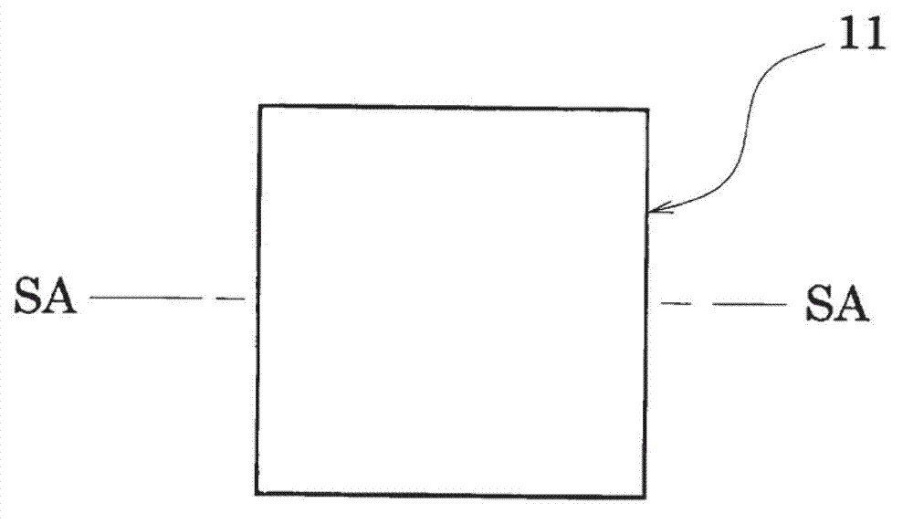
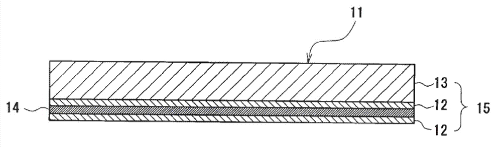
[0088] figure 1 A top view of the heat conducting sheet 11 is shown. The heat conduction sheet 11 is a component for electronic equipment with close adhesion between heating elements such as IC or CPU, or radiating elements such as heat sinks or heat pipes, and as figure 2 As shown in the sectional view of , a mesh sheet 14 is buried inside the sheet-shaped heat conduction layer 15 .

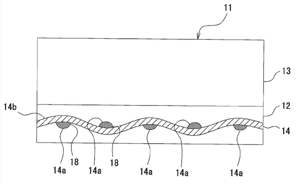
[0089] In this embodiment, in order to improve the operability, the heat conduction layer 15 adopts a double-layer structure of the adhesive layer 13 and the non-adhesive layer 12, and the mesh sheet 14 is embedded in the non-adhesive layer 12 in the heat conduction layer 15. Inside. The non-adhesive layer 12 is inserted into the mesh (through hole) formed in the grid-shaped mesh sheet 14, so that one side of the adhesive layer 13 side (interface with the adhesive layer 13) and the other surface of the outer surface side (outer surface ...

no. 2 example 〔 pic 12

[0130] In the above-mentioned embodiment, the heat conduction layer 15 has a laminated structure formed by the adhesive layer 13 and the non-adhesive layer 12, and the inside of the non-adhesive layer 12 is embedded with the mesh sheet 14, but the heat conduction sheet 21 shown in this embodiment is as follows: Figure 12 As shown, a mesh 14 is buried inside the adhesive layer 13 .

[0131] The heat conduction sheet 21 can be manufactured by the following method.

[0132] The mesh sheet 14 is embedded by the same method as the process of embedding the mesh sheet 14 in the non-adhesive layer 12 in the manufacture of the heat conduction sheet 11 shown in the previous embodiment in which the mesh sheet 14 is embedded in the non-adhesive layer 12. In the adhesive layer 13. In addition, the step of laminating the non-adhesive layer 12 on the adhesive layer 13 is performed by the same method as the step of laminating the adhesive layer 13 on the non-adhesive layer 12 . Thereby, ma...

no. 3 Embodiment 〔 pic 13

[0136] The heat conducting sheet 31 shown in this embodiment, as Figure 13 As shown, a mesh 14 is buried near the interface between the adhesive layer 13 and the non-adhesive layer 12 .

[0137] In the manufacture of the thermally conductive sheet 31 , firstly, the non-adhesive layer composition 16 constituting the non-adhesive layer 12 is coated on the film 2 . Next, on the coated non-adhesive layer composition 16 , the mesh sheet 14 is pressed and placed in an embedded manner. Subsequently, the non-adhesive layer composition 16 after dipping the mesh sheet 14 for about half a minute is coated with the adhesive layer composition 17 to form a sheet. Thereafter, by curing and molding the two thermally conductive compositions, the thermally conductive sheet 31 in which the mesh sheet 14 is embedded in the laminated interface of the non-adhesive layer 12 and the adhesive layer 13 can be obtained.

[0138] In addition, the order of the coating process of the non-adhesive layer ...


PUM

PropertyMeasurementUnit
thicknessaaaaaaaaaa
thicknessaaaaaaaaaa
thicknessaaaaaaaaaa

Abstract

Disclosed is a thermally conductive sheet which comprises a thermally conductive composition comprising a resin composition and a thermally conductive filler and a mesh sheet, both surfaces of the mesh sheet being coated with the thermally conductive composition so as to form a thermally conductive layer, and in which air bubble inclusion was eliminated to make the thermally conductive sheet have satisfactory thermal conductivity and high strength and be less apt to be torn. The mesh sheet (14) comprises filamentous materials (14a) and (14b) which cross each other to form a network, and bubble inclusion inhibition parts (18) which inhibit air bubbles from coming into the interface between the thermally conductive composition (12) and the mesh sheet (14) have been formed at the intersections where the filamentous materials (14a) and (14b) cross. The bubble inclusion inhibition parts (18) may be fusion-bonded parts (18a), press-bonded parts (18b), etc.

Description

technical field [0001] The present invention relates to a thermally conductive sheet that can be used as a thermal countermeasure against heat dissipation or cooling of electronic components included in electronic equipment, various displays, batteries, and other equipment / devices. Background technique [0002] Electronic components such as CPUs mounted in electronic equipment are heat generating bodies, and in order to cool the heat generating bodies, radiating bodies such as heat sinks are attached. Therefore, in order to promote heat conduction from the heat generating body to the heat sink, a heat conducting sheet is installed between the heat generating body and the heat sink. By using the heat conducting sheet, the heat transfer area between the heating body and the cooling body can be increased, so that the heat can be efficiently dissipated from the heating body to the cooling body. [0003] In order to reduce the thermal resistance value which is an index indicatin...

Claims


Application Information

Patent Timeline
Patent Type & Authority Applications(China)
IPC IPC(8): B32B27/12B32B27/20H01L23/36H05K7/20C09J7/29
CPCH01L2924/0002H05K7/20481H01L23/3737C09J2203/326D06N3/0063C09J2205/106D06N3/0002C08K3/0075C08K2003/2227D06N2213/045C08K3/08D06N3/0006C09J2201/602D06N2209/062C08K3/22H01L23/3733H01B7/428D06N3/0056C09J2400/263C09J7/0296C09J7/29Y10T442/176Y10T442/164C09J2301/314C09J2301/41H01L2924/00
Inventor 渡部泰佳
Owner SEKISUI POLYMATECH CO LTD
Why Eureka
Try Eureka