
Wiper

A wiper and wiper blade technology, which is applied in vehicle cleaning, vehicle maintenance, transportation and packaging, etc., can solve the problems of wiper lift and tremor, and achieve the effects of preventing lift, improving appearance and minimizing gaps

Inactive Publication Date: 2013-05-08
KWC CORP
View PDF2 Cites 3 Cited by
  • Summary
  • Abstract
  • Description
  • Claims
  • Application Information

AI Technical Summary

Problems solved by technology

[0004] This kind of wiper has the problem of lifting or chattering under the air pressure acting on the glass surface when the car is running at high speed.

Method used


Image

  • Wiper
  • Wiper
  • Wiper

Examples


Embodiment Construction

[0065] The present invention will be described in detail below with reference to the accompanying drawings. Among the components of the present invention, specific descriptions of those that can be clearly grasped and easily reproduced by those skilled in the art based on the prior art are omitted so as not to obscure the gist of the present invention.

[0066] The overall structure of the wiper assembly of the present invention

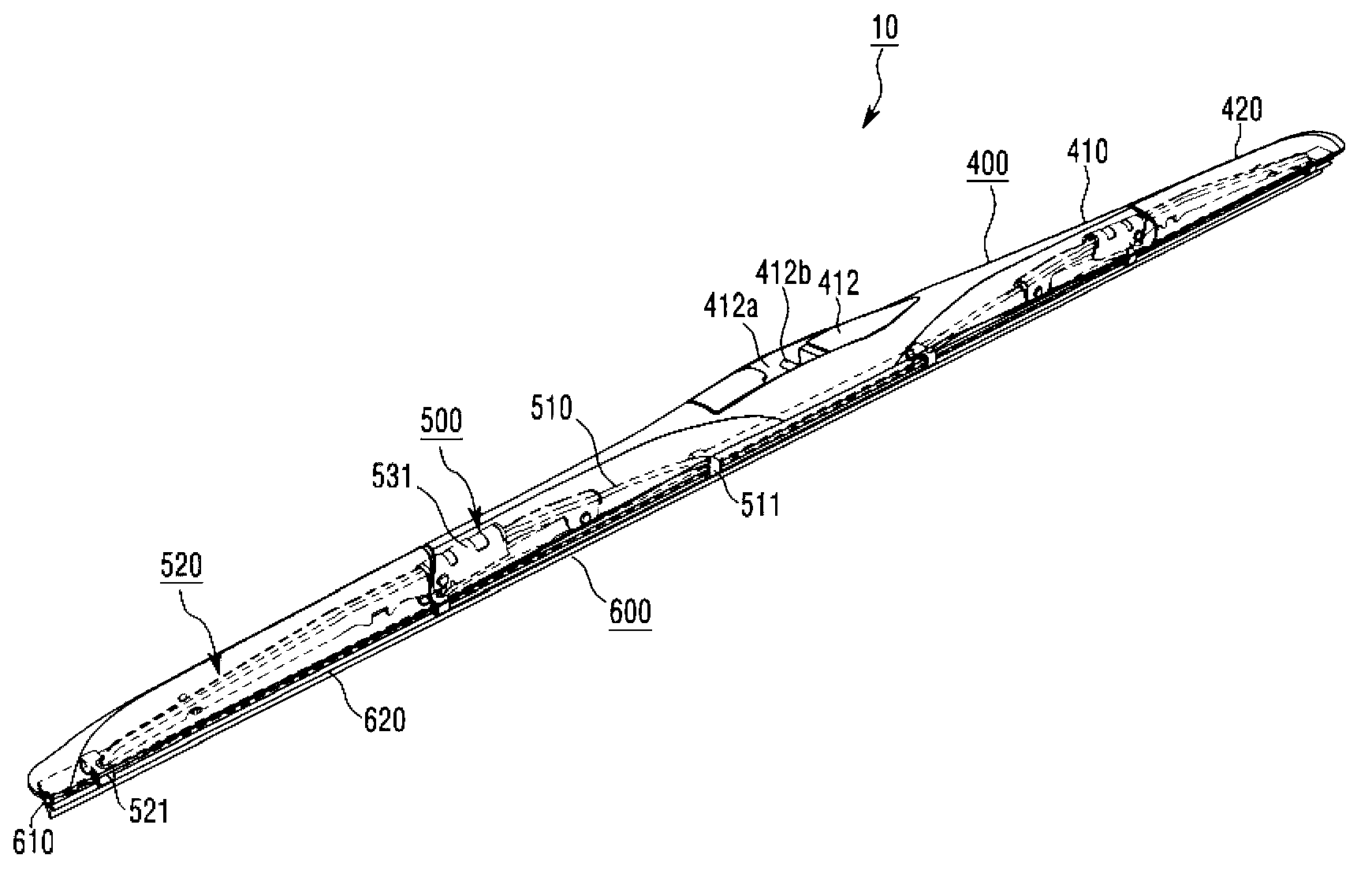
[0067] figure 1 and figure 2They are respectively a front view and a perspective view showing the wiper blade of the present invention.

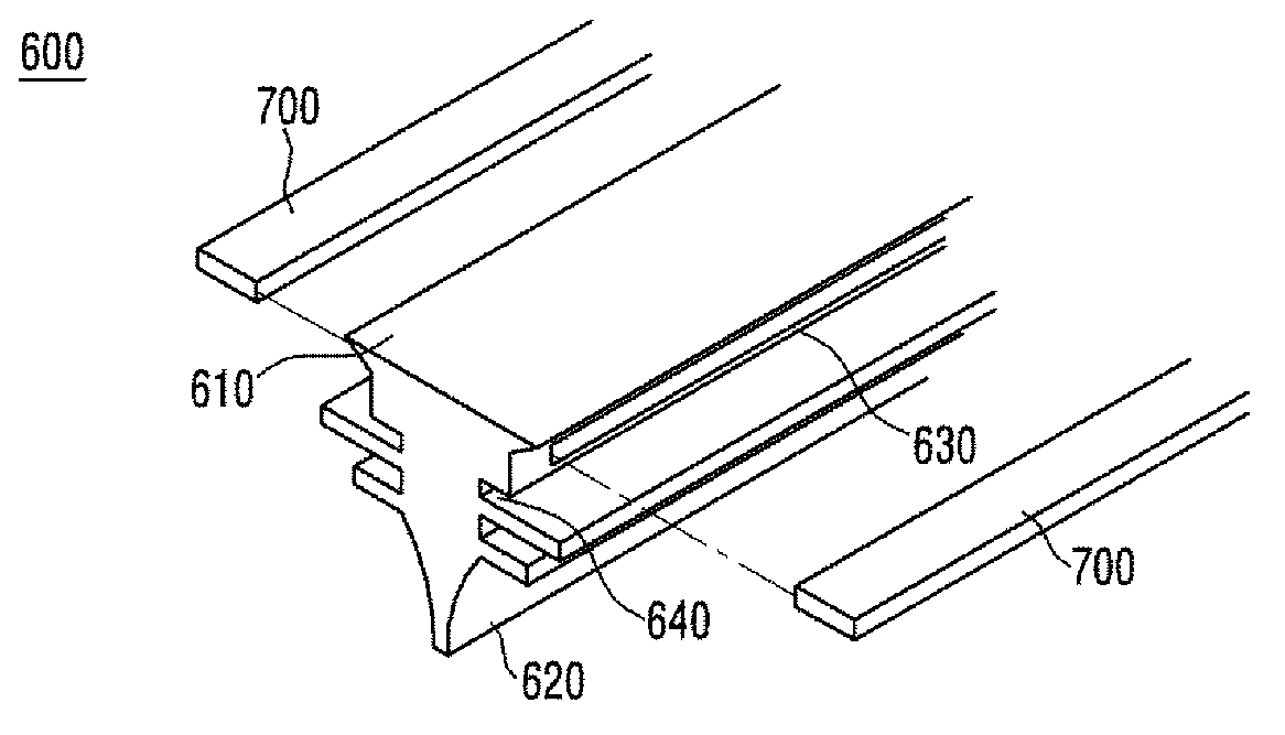
[0068] Such as figure 1 and figure 2 As shown, the wiper 10 of the present invention includes: a wiper blade 600 that is close to the glazed window surface of the vehicle and wipes the glazed window surface of the vehicle; a support rod assembly 500 that is connected into a single windshield type and supports the wiper blade 600; The cover portion 400 of the rod assembly 500 is supported.

[0069] next to...


PUM


Abstract

The invention relates to a wiper. According to an embodiment of the invention, the wiper comprises a wiper blade (600), a supporting rod assembly (500) and a cover portion (400), wherein the wiper blade (600) wipes a wipe surface directly; the supporting rod assembly (500) supports the wiper blade (600); and the cover portion accommodates the supporting rod assembly (500). The cover portion (400) comprises a fixed cover portion (410) and more than one movable cover portions (420) which can pivot relative to the fixed cover portion (410). As a result, when the movable cover portions (420) pivot, gaps between the fixed cover portion (410) and the movable cover portions (420) are minimized.

Description

technical field [0001] The present invention relates to a wiper blade, in particular to a wiper blade capable of stably wiping while an automobile is running. Background technique [0002] Generally speaking, the wiper is used to remove foreign objects or rain and snow while the car is running, so as to prevent the driver from obstructing the driver's front view. [0003] Existing wiper blades include a support rod assembly formed by connecting support rods of metal materials in a tournament shape. As for the support rod assembly, a plurality of single-elimination blade-shaped support rods bend the wiper blade mounted with the back plate to conform to the curvature of the car glass. [0004] This kind of wiper has the problem of lifting or chattering under the air pressure acting on the glass surface when the car is running at high speed. [0005] 【Background technical literature】 [0006] 【Patent Literature】 [0007] Korean patent publication 10-2010-0064983 (published ...

Claims


Application Information

Patent Timeline
Patent Type & Authority Applications(China)
IPC IPC(8): B60S1/34B60S1/40
CPCB60S2001/3843B60S1/38B60S1/3801B60S2001/3815B60S1/0491B60S1/40
Inventor 金兑庆金冠熙安在赫
Owner KWC CORP
Learn More