
Novel material picking method of aluminum extrusion machine rear portion finishing device

An aluminum extrusion and rear technology, applied in the direction of conveyors, conveyor objects, transportation and packaging, etc., can solve problems such as belt damage, uneven force on the timing belt felt, and different elongation on both sides of the belt, so as to avoid The effect of belt damage, which is conducive to the continuity of production

Active Publication Date: 2015-04-08
CHINA NAT HEAVY MACHINERY RES INSTCO
View PDF7 Cites 0 Cited by
  • Summary
  • Abstract
  • Description
  • Claims
  • Application Information

AI Technical Summary

Problems solved by technology

However, under the load condition, the timing belt felt is unevenly stressed, resulting in different elongation on both sides of the belt, and then the timing belt felt climbs up the baffles on both sides of the timing pulley, resulting in belt damage

Method used


Image

  • Novel material picking method of aluminum extrusion machine rear portion finishing device
  • Novel material picking method of aluminum extrusion machine rear portion finishing device
  • Novel material picking method of aluminum extrusion machine rear portion finishing device

Examples


Embodiment 1

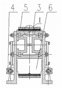
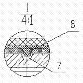
[0015] A new type of picking device for the rear finishing equipment of an aluminum extrusion machine, which includes: small synchronous pulley 1, small synchronous pulley end tensioning mechanism 2, aluminum beam 3, large synchronous pulley end tensioning mechanism 4, and synchronous belt 5 1. Large synchronous pulley 6; It is characterized in that: the middle of the upper surface of the aluminum beam 3, the circumferential middle of the large synchronous pulley 6 and the circumferential middle of the small synchronous pulley 1 are all provided with a guide groove 7, and the upper surface of the synchronous belt 5 A guide belt 8 with protrusions is arranged in the middle, and the protrusions on the guide belt 8 correspond to the guide grooves 7 .

Embodiment 2

[0017] Such as figure 1 As shown, the new material picking device for the rear finishing equipment of the aluminum extrusion machine includes: small synchronous pulley 1, small synchronous pulley end tensioning mechanism 2, aluminum beam 3, large synchronous pulley end tensioning mechanism 4, Synchronous belt 5, large synchronous pulley 6; large synchronous pulley 6 with guide groove is fixed on one end of aluminum beam 3 with guide groove through a splint, and the bottom of aluminum beam 3 with guide groove is close to large synchronous pulley 6 with guide groove On the side, a large synchronous pulley end tensioning mechanism 4 is installed, which is composed of a guide wheel, a threaded push rod and a nut. The small synchronous pulley 1 with guide groove is installed on the other end of the aluminum beam 3 with guide groove through a splint, and the small synchronous pulley 1 with guide groove has a small synchronous pulley end tensioning mechanism 2 on the wheel shaft. Co...


PUM


Abstract

The invention relates to a novel material picking structure and a novel material picking method of an aluminum extrusion machine rear portion finishing device. The novel material picking structure comprises a small synchronous pulley (1), a small synchronous pulley end tensioning mechanism (2), an aluminum beam (3), a big synchronous pulley end tensioning mechanism (4), a synchronous belt (5) and a big synchronous pulley (6). The novel material picking structure is characterized in that guide grooves (7) are respectively formed in the middle portions of the upper surface of the aluminum beam (3), the periphery of the big synchronous pulley (6) and the periphery of the small synchronous pulley (1), a guide belt (8) with protrusions is arranged in the middle of the synchronous belt (5), and the protrusions on the guide belt (8) corresponds to the guide grooves. Due to the fact that the aluminum beam with the guide groove, the synchronous pulley with the guide groove and the synchronous belt with the guide belt are adopted, off tracking can not happen on the synchronous belt in the process of overloading transmission, the belts are prevented from being damaged, and production continuity is benefited.

Description

technical field [0001] The invention relates to a heavy metallurgical mechanical equipment, in particular to a new material picking method for finishing equipment at the rear of an aluminum extrusion machine. Background technique [0002] At present, in the rear finishing equipment of the existing large-scale aluminum extrusion machine, the structure of picking materials adopts the traditional synchronous belt felt transmission structure, which is composed of synchronous belt pulley, baffles on both sides of the synchronous belt wheel, synchronous belt felt, aluminum Composed of beams and tensioning mechanisms. With this kind of picking structure, under no load, the synchronous belt felt can be transmitted by adjusting the tension mechanism. However, under the condition of belt load, the timing belt felt is unevenly stressed, resulting in different elongation on both sides of the belt, and then the timing belt felt climbs up the baffles on both sides of the timing pulley, r...

Claims


Application Information

Patent Timeline
Patent Type & Authority Patents(China)
IPC IPC(8): B65G21/22B65G39/071B65G15/30
Inventor 张君李正利薛菲菲陈永甲黄胜段丽华
Owner CHINA NAT HEAVY MACHINERY RES INSTCO
Learn More