
Coil winder wire-guiding device

A winding machine and wire technology, applied in the direction of transportation and packaging, delivery of filamentous materials, thin material processing, etc., can solve the problems of uneven ends, uneven wire spacing, low efficiency, etc., to achieve wire coil The density is consistent, the effect of improving quality and aesthetics

Inactive Publication Date: 2013-05-08
周建江
View PDF0 Cites 1 Cited by
  • Summary
  • Abstract
  • Description
  • Claims
  • Application Information

AI Technical Summary

Problems solved by technology

[0002] At present, the storage, arrangement, and storage of flexible wires are all rolled into cylinders by winding machines. The existing winding machines mainly use the wires to be unwound from the pay-off wheel, pass through the guide wheel, and wind up on the take-up wheel. Among them, the wire take-up wheel only has a single rotation function, and there is no other auxiliary device to arrange the wires in an orderly manner, so that each time the layer is changed, a large wire displacement angle will be generated, and eventually the wire distance of each layer of the wound wire coil will be different. Uniformity, irregular ends, slow winding speed, low efficiency, greatly affecting product quality and production efficiency

Method used


Image

  • Coil winder wire-guiding device
  • Coil winder wire-guiding device

Examples


Embodiment Construction

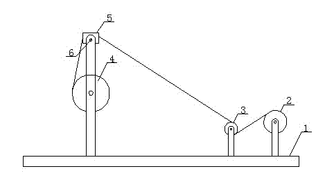
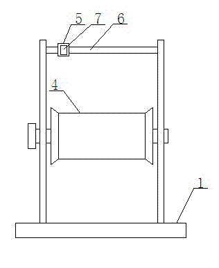
[0013] like figure 1 It is a structural schematic diagram of the present invention, figure 2 It is a schematic diagram of the connection of the pulleys of the present invention, a wire device of a wire winding machine, including a bracket 1, a pay-off wheel 2, a guide wheel 3 and a take-up wheel 4, and the pay-off wheel 2, the guide wheel 3 and the take-up wheel 4 are arranged and installed in sequence On the support 1 , a slider 5 is arranged above the take-up wheel 4 . Slide block 5 is enclosed within on a slide bar 6. Slide bar 6 is parallel to take-up reel 4, and take-up reel 4 isometric. The slider 5 is provided with a displacement sensor 7 .

[0014] A slider 5 is set above the take-up wheel 4 to guide the displacement of the wire. The slider 5 is provided with a displacement sensor 7. During the uniform motion process, when it encounters the brackets 1 at both ends, it will automatically turn back and reciprocate, driving the wire to move freely. Sequential arrange...


PUM


Abstract

The invention relates to the technical field of winding equipment, in particular to a coil winder wire-guiding device which comprises a support, an unwinding wheel, a wire-guiding wheel and a winding wheel. The unwinding wheel, the wire-guiding wheel and the winding wheel are sequentially mounted on the support. A sliding block is arranged above the winding wheel to guide the movement of wires, and is provided with a movement sensor. In a progress of uniform motion, the sliding block returns back automatically when touching two ends of the support, and moves back and forth to drive the wires to be arranged in sequence and shifts layers automatically, so that the wound coil is natural in density and neat and even, and quality and appearance of products are improved.

Description

technical field [0001] The invention relates to the technical field of winding equipment, in particular to a wire device for a winding machine. Background technique [0002] At present, the storage, arrangement, and storage of flexible wires are all rolled into cylinders by winding machines. The existing winding machines mainly use the wires to be unwound from the pay-off wheel, pass through the guide wheel, and wind up on the take-up wheel. Among them, the wire take-up wheel only has a single rotation function, and there is no other auxiliary device to arrange the wires in an orderly manner, so that each time the layer is changed, a large wire displacement angle will be generated, and eventually the wire distance of each layer of the wound wire coil will be different. Uniformity, uneven ends, slow winding speed, low efficiency, greatly affect product quality and production efficiency. Contents of the invention [0003] In order to overcome the defects of the existing win...

Claims


Application Information

Patent Timeline
IPC IPC(8): B65H54/30
Inventor 周建江
Owner 周建江
Learn More