Cooling method of a direct reduction vertical furnace

A cooling method and shaft furnace technology, which is applied to shaft furnaces, furnaces, furnace types, etc., can solve problems such as energy loss, and achieve the effects of reducing water volume, reducing reducing gas, and reducing outlet temperature

Inactive Publication Date: 2013-05-08
CISDI ENG CO LTD +1
View PDF2 Cites 4 Cited by
  • Summary
  • Abstract
  • Description
  • Claims
  • Application Information

AI Technical Summary

Problems solved by technology

This small cycle cooling method reduces the heat released by the sponge iron from 850°C to 50°C by the cooling air, resulting in a serious loss of energy

Method used


Image

  • Cooling method of a direct reduction vertical furnace

Examples


Embodiment

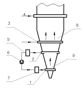
[0014] Embodiment, a kind of cooling method of direct reduction shaft furnace, such as figure 1 As shown, a part of the cooling air enters the shaft furnace from the cooling air inlet 3 in the upper part of the cooling section. The cooling air is at normal temperature. At the same time, the temperature of the cooling gas rises to 750-800 °C, rises to the reduction section and mixes with the reduction gas 4 to reduce the iron ore. A cooling gas distributor is installed in the upper part of the cooling section 8 to ensure the cooling of the shaft furnace. The air is evenly distributed along the axial direction; another part of the cooling air is passed into the shaft furnace from the cooling air inlet 1 of the lower part 9 of the cooling section. It enters the shaft furnace from the opening, and the cooling air that passes into the lower part 9 of the cooling section exchanges heat with the sponge iron at about 400 °C cooled by the upper part 8 of the cooling section. The sponge...


PUM


Abstract

The invention relates to a cooling method of a direct reduction vertical furnace which is characterized in that cooling gas is divided into two parts, and the two parts enter a cooling section; one part of the cooling gas enters the vertical furnace from the upper part of the cooling section; the part of cooling gas is heated by hot sponge iron when cooling the sponge iron, and participates in a reduction reaction in a reduction section; the other part of the cooling gas enters the vertical furnace from the lower part of the cooling section, and further cools the sponge iron; the part of cooling gas is led out through a cooling gas outlet pipe arranged in the middle part of the cooling section. According to the invention, cooling gas is divided into two parts, and two-stage cooling is adopted, such that high-temperature section sponge iron energy is fully utilized, circulation cooling gas is reduced, tuyere-section reduction coal gas inlet amount is reduced, reduction coal gas needed to be heated is reduced, cooling gas outlet temperature is reduced, cooling gas washing water amount is reduced, gas amount for pressurization and dehumidification is reduced, energy consumption during the production process is reduced, and energy is saved.

Description

technical field [0001] The invention relates to a cooling method, in particular to a cooling method for a direct reduction shaft furnace. Background technique [0002] Direct reduced iron is obtained by direct reduction of iron ore under solid conditions. It has the advantages of stable composition, low harmful impurities, and uniform particle size. It can be used as a pure raw material for smelting high-quality steel and special steel. Iron-containing raw materials for metallurgy and other processes. [0003] At present, the direct reduction shaft furnace is mainly composed of a reduction section and a cooling section. After preheating, the reduction gas enters the reduction section through the shaft furnace surrounding pipe to complete the reduction reaction of the ore; the cooling gas at room temperature is pressurized and enters the shaft furnace from the lower part of the shaft furnace cooling section. , to exchange heat with the hot reduced iron in the shaft furnace t...

Claims


Application Information

Patent Timeline
Patent Type & Authority Applications(China)
IPC IPC(8): C21B13/02
Inventor 宋华吕遐平金明芳尹慧超张涛倪晓明陈凌
Owner CISDI ENG CO LTD
Why Eureka
Try Eureka