
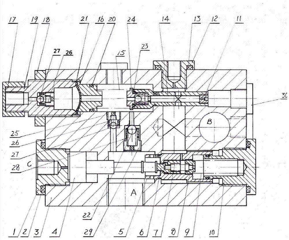
Balance valve of dynamic load differential pressure protection and flow pressure air chamber compensation

A technology of flow pressure and balance valve, applied in the field of balance valve, which can solve the problems of pressure loss and energy consumption, system heating, uncontrolled drop of the boom, etc.

Inactive Publication Date: 2013-05-08
杨洁
View PDF0 Cites 10 Cited by
  • Summary
  • Abstract
  • Description
  • Claims
  • Application Information

AI Technical Summary

Problems solved by technology

This design brings two problems in use: one is the opening pressure of 1.15 times the rated working pressure minus the very low oil return pressure, the pressure difference of the orifice is too large, and the small opening of the orifice will cause the oil cylinder The oil in the support cavity loses pressure rapidly, causing the boom to fall out of control
Although this method can alleviate the uncontrolled slide of the boom caused by the poor stability of the relief valve under certain conditions, it will bring huge pressure loss and energy consumption to the system under normal boom retraction conditions, causing the system to heat up. Damage to the sealing performance of the working medium and hydraulic system

Method used


Image

  • Balance valve of dynamic load differential pressure protection and flow pressure air chamber compensation

Examples


Embodiment Construction

[0008] The specific implementation of the balance valve of the present invention is: Sealing working condition: the high-pressure oil in chamber B passes through the small hole at the right end of the main valve core 5, and communicates with the spring chamber at the right end of the main valve core 5, and the one-way valve core 6 is connected with the main valve core. The cores 5 are all locked with their sealing seats under the action of the high-pressure oil and their respective springs, closing the flow channel of the high-pressure oil in the B cavity to the A cavity. The hydraulic oil flows from chamber A to chamber B, the one-way valve core 6 is closed under the action of the small spring 7, the right chamber of the main valve core 5 is in communication with chamber B, and the hydraulic oil in chamber A pushes the main valve core 5 together with the one-way spool 6 compresses the main spring 9 to move to the right, the throttle hole on the small cylindrical sleeve at the ...


PUM


Abstract

Disclosed is a balance valve of dynamic load differential pressure protection and flow pressure air chamber compensation. The balance valve of dynamic load differential pressure protection and flow pressure air chamber compensation is composed of combination of the balance valve, a two-level protection overflow valve and a pressure flow compensator. The balance valve is characterized in that a one-way valve core (6) is installed in a hole of a main valve core (5) in a sleeved mode. A right end spring cavity controlling the main valve core (5) is composed of a hydraulic control one-way valve whether is communicated with an A cavity or a B cavity. Several uniformly distributed axial direction small grooves are arranged in a large cylinder at the right end of the main valve core (5) in an opening mode. A holding cavity is communicated with the A cavity and is arranged between a main spring seat (10) and a valve body (3). The two-level overflow valve is characterized in that a throttling opening of the two-level overflow valve is the combination that a fixing throttling opening and a variable throttling opening are in series connection. The pressure flow compensator is arranged on the left cavity of an overflow valve core (14). The control principle of opening the differential pressure protection is that opening of the overflow valve core (14) is controlled by the difference value of surge pressure of the B cavity and lifting pressure of an oil cylinder. The balance valve of dynamic load differential pressure protection and flow pressure air chamber compensation is beneficial to the fact that an arm frame is returned after the surge pressure trigger by a dynamic load is released and the vibration and the swaying which are possible to emerge of the arm frame can be avoided.

Description

1. Technical field: [0001] The invention relates to a balance valve for dynamic load pressure difference protection and flow pressure air chamber compensation. This balance valve is especially suitable for concrete pump trucks with high precision, high pressure and high sealing life and reliability requirements, and also suitable for other various heavy machinery equipment. 2. Background technology: [0002] With the development of heavy machinery and equipment, some new requirements are put forward for the performance of the balance valve. For example, in order to protect the structural safety of the boom of the concrete pump truck under the There is a difference requirement of about 15% between the opening pressure and closing pressure of the flow valve. These are not available in domestic balance valves at present, which has led to the long-term dependence of such products on imported accessories and hindered the development of my country's main engine equipment. In add...

Claims


Application Information

Patent Timeline
IPC IPC(8): F15B13/02
Inventor 杨洁
Owner 杨洁
Learn More