Diaphragm positioning structure and backlight module thereof

A positioning structure and diaphragm technology, applied in the direction of optics, electric light source, light source fixing, etc., can solve the problems of diaphragm warping and deformation, and achieve the effect of improving optical taste

Active Publication Date: 2013-05-08
TCL CHINA STAR OPTOELECTRONICS TECH CO LTD
View PDF4 Cites 21 Cited by
  • Summary
  • Abstract
  • Description
  • Claims
  • Application Information

AI Technical Summary

Problems solved by technology

[0005] The purpose of the present invention is to provide a diaphragm positioning structure to solve the problem of warping and deformation of the diaphragm caused by the expansion and c

Method used


Image

  • Diaphragm positioning structure and backlight module thereof
  • Diaphragm positioning structure and backlight module thereof
  • Diaphragm positioning structure and backlight module thereof

Examples


Embodiment 1

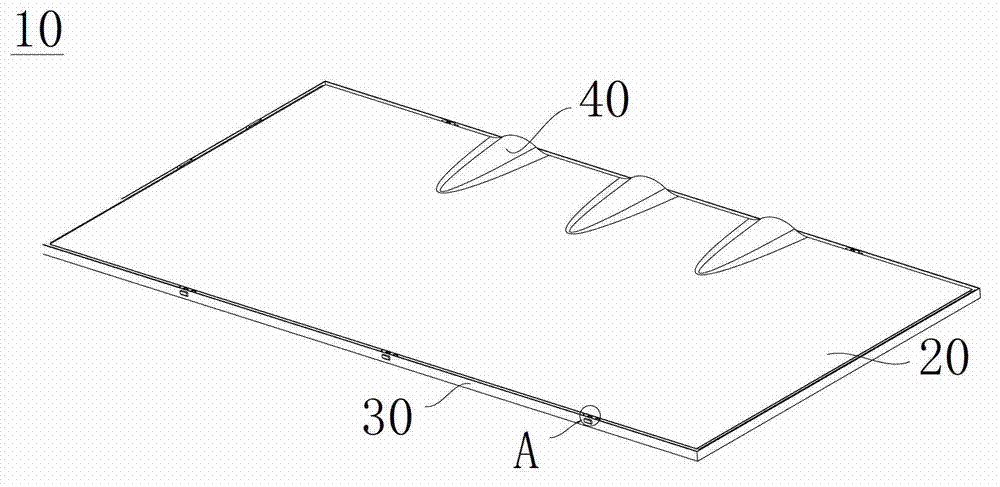
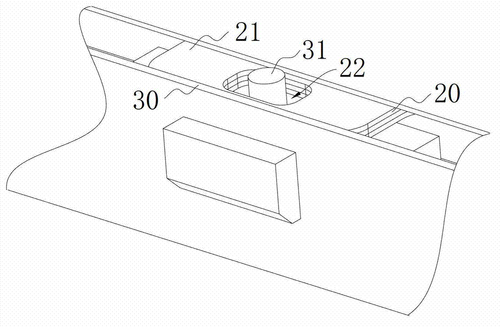
[0034] Please refer to Figure 3 to Figure 7 , the backlight module of the present invention is used in display devices, such as Figure 4 As shown, the backlight module 100 includes a film positioning structure 200 , a light guide plate 300 fixed in the film positioning structure 200 , and a backlight (not shown). The diaphragm positioning structure 200 includes a diaphragm 210, a positioning frame 220 and a slider 250, wherein the diaphragm 210 is an optical diaphragm, and the function of the optical diaphragm is to improve the optical uniformity of the backlight module 100 in the liquid crystal display device, so that the backlight The module 100 can generate the best light source distribution and improve the image quality. In this embodiment, the edge of the diaphragm 210 has at least one lug 211 , and a positioning hole 212 is formed in the middle of the lug 211 , wherein the positioning hole 212 is a perforation.

[0035] In a liquid crystal display device, usually a p...

Embodiment 2

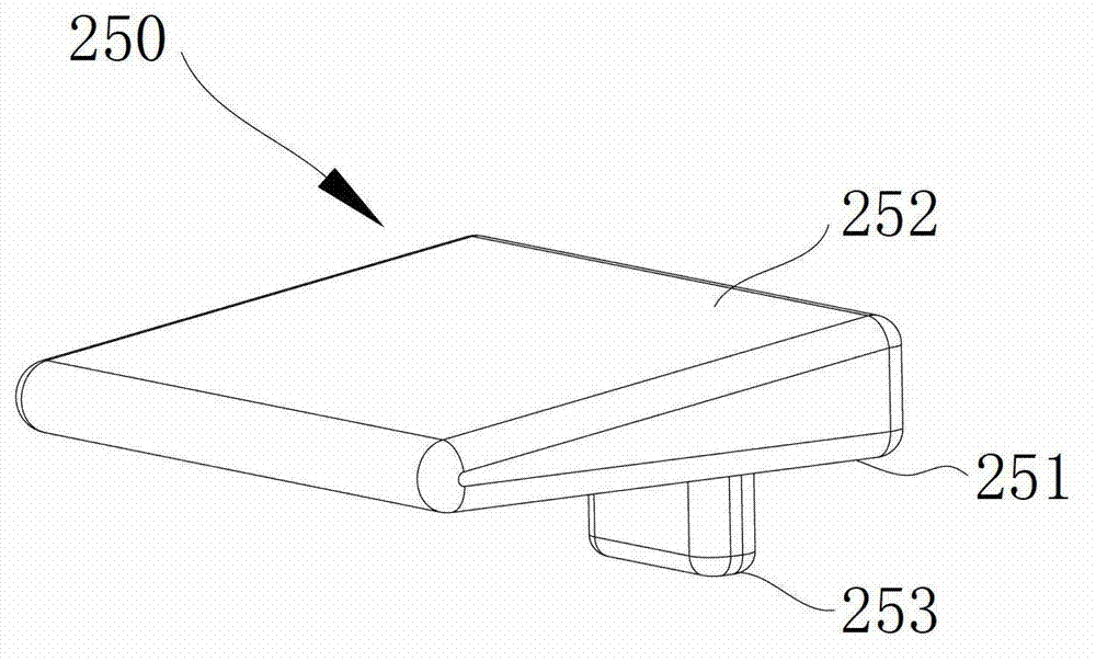
[0041] Please refer to Figure 8 to Figure 12 , only the differences between Embodiment 2 and Embodiment 1 will be described below. Such as Figure 9 As shown, in Embodiment 2, the difference is that the positioning frame 220 not only includes the back frame 230 and the plastic frame 240, but also includes an insert block 243 with a slope, and the insert block 243 is arranged on the lower surface of the top plate 241, The slope of the inserting block 243 is the first slope 242 . Wherein, in order to better control the sliding direction and sliding distance of the sliding block 250 , a positioning slide groove 270 is formed on the bottom plate 231 so that the sliding block 250 can slide toward a preset track. In order to realize the purpose that the slider 250 can slide to the preset track, especially, as Figure 8 As shown, the slider 250 is provided with a corresponding engaging protrusion 260 on the bottom surface 251, and the positioning protrusion 253 is disposed on the...


PUM


Abstract

The invention discloses a diaphragm positioning structure and a backlight module thereof. The positioning structure is used for positioning a diaphragm, and at least one positioning hole is formed in the diaphragm. The diaphragm positioning structure further comprises a positioning framework provided with a first slope facing the diaphragm and a slide block. The slide block is located between the positioning framework and the diaphragm and is provided with a bottom face which contacts with the diaphragm, and a second slope which correspondingly contacts with the first slope. The obliquity of the second slope is gradually raised towards the direction of the outer edge of the diaphragm. A positioning protrusion corresponding to the positioning hole is arranged on the outer edge of the slide block, and the positioning protrusion is arranged in the positioning hole in a penetrating mode. By means of the mutual extrusion between the slope of the positioning frame and the slope of the slide block in the diaphragm positioning structure, the slide block moves towards the outer side of the diaphragm, and the positioning protrusion is used for hanging the positioning hole to exert an outward tensile stress on the diaphragm to tension the diaphragm,. The invention further provides another connecting structure of the slide block and the positioning frame. Through utilization of the slide block to exert the tensile stress on the diaphragm, the harmomegathus quantity of the diaphragm due to temperature change can be adjusted to solve the problem of warping of the diaphragm.

Description

technical field [0001] The invention belongs to the field of liquid crystal display, and more specifically relates to a diaphragm positioning structure and a backlight module thereof. Background technique [0002] Since a liquid crystal display (Liquid crystal display, LCD) has many advantages, the liquid crystal display has been widely used in various electronic devices in recent years. [0003] In the liquid crystal display device, since the liquid crystal itself does not have light-emitting properties, it is necessary to provide the liquid crystal display device with a backlight. In the backlight module, the optical film near the backlight will be warped and deformed due to the heat emitted from the backlight, which makes the display brightness, uniformity, contrast and viewing angle of the liquid crystal display device important. The characteristics are deeply affected by the backlight module. In the liquid crystal display with LED as the backlight source, in order to ...

Claims


Application Information

Patent Timeline
IPC IPC(8): F21V17/10F21S8/00G02F1/13357
CPCG02F1/1335G02F1/1333G02F1/133308G02F1/133317G02F1/133322
Inventor 周革革李德华
Owner TCL CHINA STAR OPTOELECTRONICS TECH CO LTD
Why Eureka
Try Eureka