High energy efficiency dry shell and tube condensing heat exchanger with tube for subcooling

A condensing heat exchanger, high energy-efficiency technology, applied in subcoolers, evaporators/condensers, refrigerators, etc., can solve problems such as difficulty in meeting production requirements, increase in internal condensing temperature, and increase in external load, and achieve overall The effect of reducing the adverse factors of circulation, improving the efficiency of condensation heat exchange, and reducing the load of the refrigerant

Inactive Publication Date: 2013-05-08
SHANGHAI HANYE REFRIGERATION MACHINERY
View PDF8 Cites 1 Cited by
  • Summary
  • Abstract
  • Description
  • Claims
  • Application Information

AI Technical Summary

Problems solved by technology

Due to the influence of unfavorable factors such as the increase of the condensation temperature on the refrigerant side in the existing brine process, the temperature of the outlet water will increase accordingly, and the external load will increase. At the same time, the thermal resistance coefficient of the dirt will continue to increase, and then the cycle will affect the refrigeration. Heat transfer efficiency on the agent side
[0004] The existing shell-and-tube condensing heat exchanger cannot fully condense the refrigerant after cooling, the internal condensation temperature increases, the load of the brine increases continuously, and the cycle of unfavorable factors increases, so that the heat transfer coefficient per unit volume decreases continuously, and the heat transfer Efficiency continues to decrease, making it difficult to meet production requirements

Method used


Image

  • High energy efficiency dry shell and tube condensing heat exchanger with tube for subcooling
  • High energy efficiency dry shell and tube condensing heat exchanger with tube for subcooling
  • High energy efficiency dry shell and tube condensing heat exchanger with tube for subcooling

Examples


Embodiment Construction

[0013] Below in conjunction with accompanying drawing and specific embodiment the present invention is described in further detail:

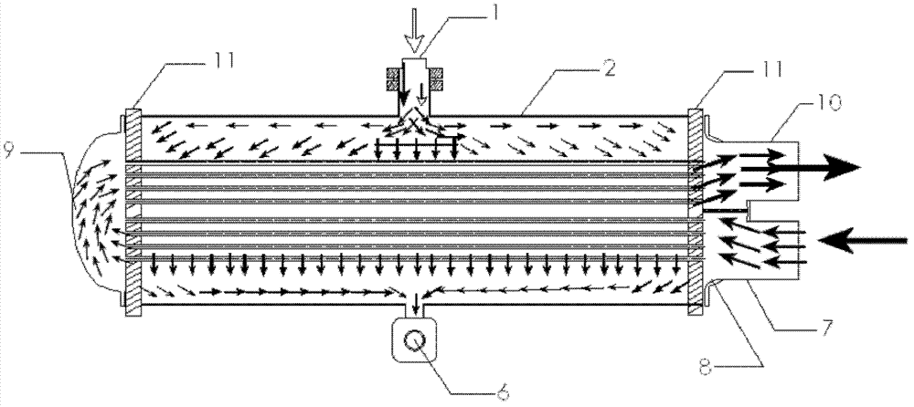
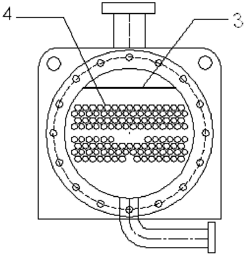
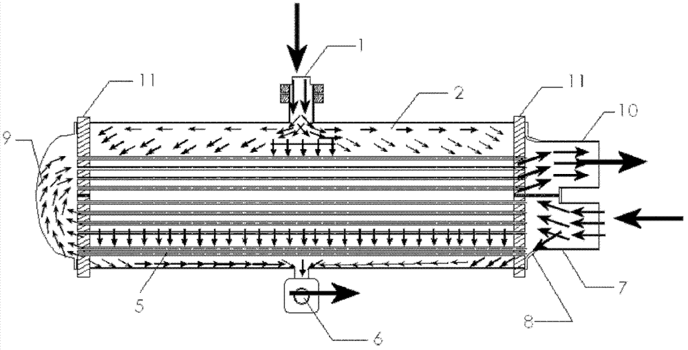
[0014] Depend on Figure 2A , Figure 2B It can be seen that the present invention includes: a casing group 2; a heat exchange tube core group 4 is fixedly placed in the casing group 2; the two ends of the heat exchange tube core group 4 are fixed on the end plate 11 by expansion joint; Above the heat exchange tube core group 4 is a dispersing plate 3; the top of the shell group 2 is provided with a refrigerant inlet 1, and the bottom end is provided with a refrigerant liquid outlet 6; one side of the shell group 2 An end cover 8 is arranged, a brine inlet 7 is arranged on its lower part, and a brine outlet 10 is arranged on its upper part; an end cover 9 without a partition plate is arranged on the other side of the shell group 2; Cooling tube core group 5 ; the supercooled tube core group is fixedly placed in the shell group 2 and at the low...


PUM


Abstract

The invention relates to a high energy efficiency dry shell and tube condensing heat exchanger with tube for subcooling. The high energy efficiency dry shell and tube condensing heat exchanger with tube for subcooling comprises a shell group and a tube core group for subcooling, wherein a heat exchange tube core group is fixedly disposed in the shell group, expanded joints at the two ends of the heat exchange tube core group are fixed on the end plates, a dispersion plate is disposed above the heat exchange tube core group, a refrigerant inlet is formed at the top end of the shell group, a refrigerant outlet is formed at the bottom end of the shell group, an end cover is arranged on one side of the shell group, a secondary refrigerant inlet is formed at the lower portion of the shell group, a secondary refrigerant outlet is formed at the upper portion of the shell group, an end cover without splitter plates is installed on the other side of the shell group, and the tube core group for subcooling is fixedly disposed in the shell group and under the heat exchange tube core group. The high energy efficiency dry shell and tube condensing heat exchanger with tube for subcooling has the advantages that because the tube core group for subcooling is installed in the heat exchanger, the degree of subcooling of refrigerants is improved, condensing temperature is decreased, the efficiency of condensing heat exchange is improved, the load of the secondary refrigerants is reduced, and negative factors of overall cyclicity is reduced.

Description

technical field [0001] The invention relates to a shell-and-tube condensation heat exchanger used in an air-conditioning system, in particular to the structure of the dry shell-and-tube condensation heat exchanger. Background technique [0002] Depend on Figure 1A , Figure 1B It can be seen that the shell-and-tube condensing heat exchanger is composed of a shell group 2, a heat exchange tube core group 4, an end plate 11, an end cover 8, and water inlet and outlet pipes. The shell is mostly cylindrical, and the heat exchange tube core group is installed inside, and the two ends of the tube core are fixed on the end plate by expansion joints. There are two kinds of hot and cold fluids for heat exchange, the brine flows in the tube from the brine inlet 7, and the other high-temperature refrigerant flows into the shell group 2 in gas form from the refrigerant inlet 1, and is dispersed by the dispersion plate 3 Finally, the heat exchange tube core group 4 flows outside the t...

Claims


Application Information

Patent Timeline
Patent Type & Authority Applications(China)
IPC IPC(8): F25B39/04F25B40/02
Inventor 卢大民
Owner SHANGHAI HANYE REFRIGERATION MACHINERY
Why Eureka
Try Eureka