Refrigeration utensil

A technology for refrigeration appliances and storage containers, which can be used in household refrigeration equipment, household appliances, lighting and heating equipment, etc., and can solve problems such as space waste

Active Publication Date: 2013-05-08
BSH ELECTRICAL APPLIANCES JIANGSU
View PDF6 Cites 12 Cited by
  • Summary
  • Abstract
  • Description
  • Claims
  • Application Information

AI Technical Summary

Problems solved by technology

Inevitably, the space b

Method used


Image

  • Refrigeration utensil
  • Refrigeration utensil
  • Refrigeration utensil

Examples


Embodiment Construction

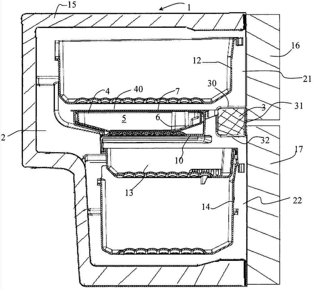
[0022] Please refer to the attached drawings, first of all please refer specifically figure 1 . The refrigerating appliance 1 includes a box 15 having a heat-insulating storage chamber 2. The storage compartment 2 has a front opening opening for taking out food from the storage compartment 2 or placing food in the storage compartment 2 through the taking out opening.

[0023] The box 15 includes a beam 3 at the front end of the storage room 2. The two ends of the cross beam 3 are respectively fixed to a corresponding side wall of the box body 15 and straddle the front end of the storage room 2. In this way, the access opening of the storage room 2 is divided by the cross beam 3 into an upper access opening 21 located above the cross beam 3 and a lower access opening 22 located below the cross beam 3.

[0024] The upper access opening 21 and the lower access opening 22 are respectively closed by doors 15 and 16 at the front end of the box 15. The lower end of the door 15 and the ...


PUM


Abstract

The invention relates to a refrigeration utensil which comprises a heat-insulated storage chamber (2) and a cross beam (3) located at the front end of the storage chamber (2). The refrigeration utensil further comprises a storage container (4) which is located at the rear of the cross beam (3) and overlapped with at least parts of the cross beam (3) along the front and rear direction, the storage container (4) comprises a box (6) and a cover (7), the box (6) is provided with storage space (5) which is upwards opened, and the cover (7) is used for closing at least parts of the storage space (5).

Description

[Technical Field] [0001] The present invention relates to a refrigeration appliance, in particular to a household or commercial refrigeration appliance. [Background technique] [0002] In a known traditional refrigeration appliance, storage rooms with different storage conditions (for example, a refrigerator compartment and a freezer compartment) are separated by heat-insulating partition walls. These storage compartments can be closed by a common door or be closed by different The door is closed. For example, in a two-door refrigerator with a refrigerator compartment and a freezer compartment distributed up and down, the refrigerator compartment door and the freezer compartment door respectively close the corresponding storage compartments and respectively abut on the front end surface of the thermal insulation wall. [0003] In another known refrigeration appliance, such as disclosed in CN1162732A, the refrigeration appliance includes a storage compartment provided with a beam a...

Claims


Application Information

Patent Timeline
IPC IPC(8): F25D25/02
Inventor 鲁松涛丁渊余刚王巧
Owner BSH ELECTRICAL APPLIANCES JIANGSU
Why Eureka
Try Eureka