Diagnostic method of space gridding structure node bolt loosening injury
A bolt loosening and spatial grid technology, applied in the field of bolt loosening damage diagnosis of structures, can solve the problems of simulated damage sample combination explosion, limited measured data, and reduce neural network, achieve good generalization ability, enhance practicability, reduce effect of quantity
- Summary
- Abstract
- Description
- Claims
- Application Information
AI Technical Summary
Problems solved by technology
Method used
Image
Examples
specific Embodiment approach
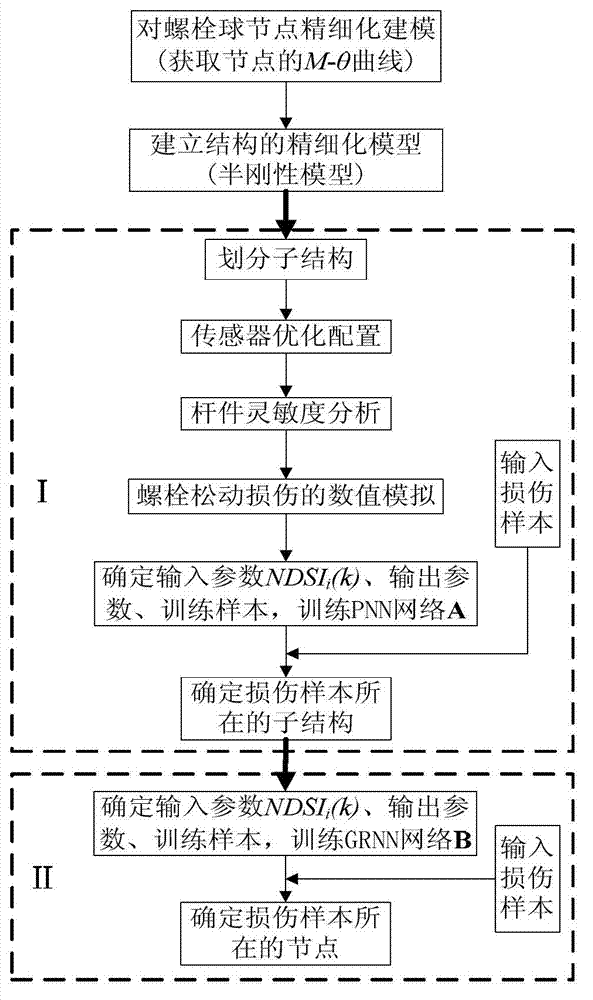
[0041] see figure 1 As shown, it is a flow chart of the diagnostic method of the present invention, wherein "I" in the figure represents "primary positioning of the substructure (taking the whole structure as the research object)" and "II" represents "node positioning (taking the whole substructure as the research object)" )".
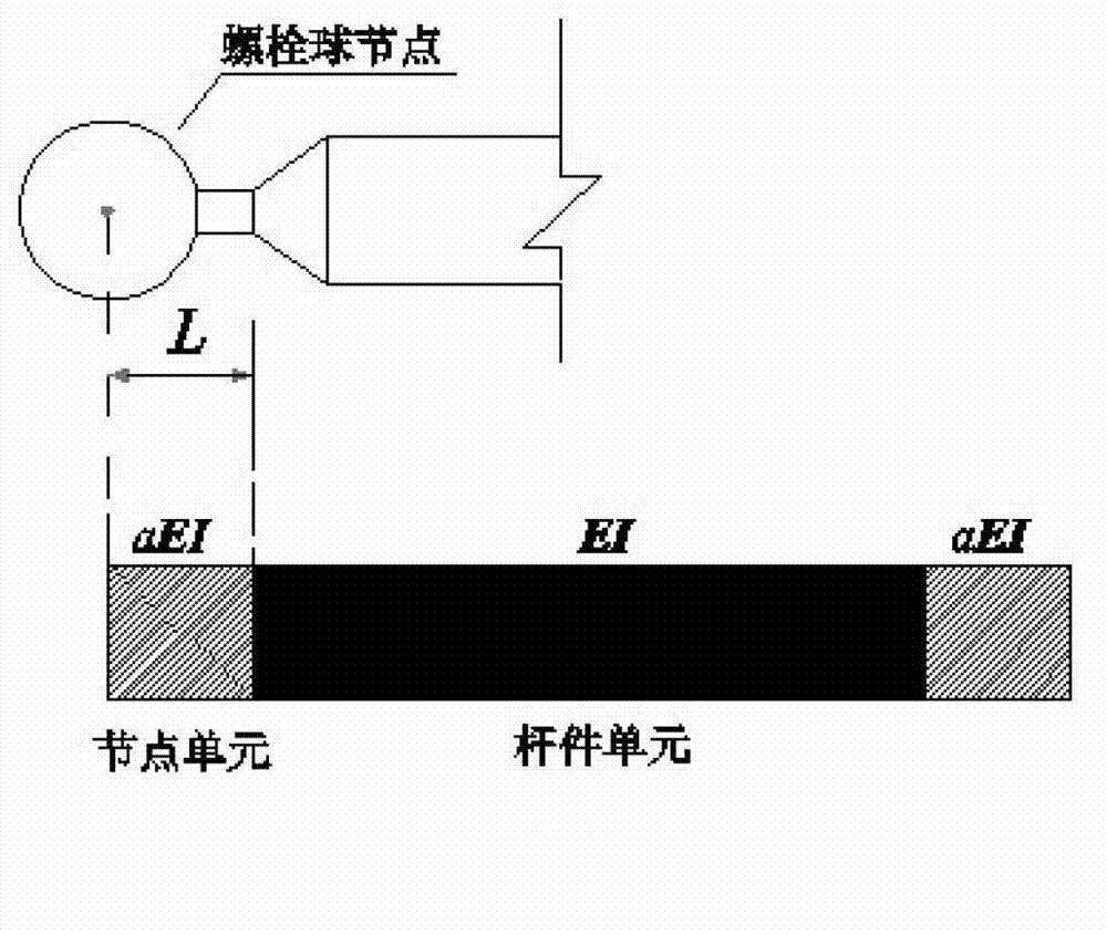
[0042] The diagnostic method mainly includes: finely modeling the bolted ball joints, and obtaining the moment-rotation angle (M―θ) curve of the bolted ball connection by analyzing the variation of the bolted ball rotational stiffness with the bending moment, and using the principle of simplification to The connection is equivalent to a straight rod;
[0043] Establish a semi-rigid model of the structure, that is, obtain a refined model of the structure;
[0044] According to the composition characteristics of the spatial grid structure, it is divided into multiple substructures according to the continuity of geometric positions, and numbered;
[00...
Embodiment 1
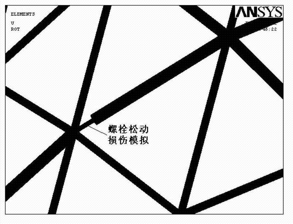
[0050] The experimental model of a single-layer cylindrical reticulated shell is composed of 157 nodes and 414 rods. The numerical model is as follows: Figure 4 shown. The cross-sectional area of the node element in the structure is reduced due to bolt loosening damage (the inner and outer radii are reduced at the same time), but the wall thickness of the bar is kept unchanged for simulation, and its elastic modulus is assumed to be unchanged. All state calculations are completed by the finite element software ANSYS. The following are the steps of member damage identification:
[0051] (1) The bolted ball joint is modeled in detail, and the bending moment-rotation angle (M―θ) curve of the bolted ball joint is obtained by analyzing the variation of the rotational stiffness of the bolted ball with the bending moment, as shown in Figure 5 shown;
[0052] (2) Establish a semi-rigid model of the structure, that is, obtain a refined model of the structure;
[0053] (3) Divis...
Embodiment 2
[0069] From the test model of single-layer cylindrical reticulated shell in Example 1, the dynamic characteristics of the first three modes before and after bolt loosening and damage were tested by using the sinusoidal excitation method. The damage location of the test model is located in "substructure 7", such as Figure 6 As shown, the position of the node is as follows Figure 7 As shown in Fig. 1, artificially loosen the bolts at their positions to simulate damage. The establishment of training samples, input parameters, output parameters and neural network is the same as that in Embodiment 1.
[0070] The substructure positioning results of the test model bolt loosening damage diagnosis are as follows: Figure 8 Shown; the node positioning results of the bolt loosening damage diagnosis of the test model are as follows Figure 9 shown.
PUM
 Abstract
Description
Claims
Application Information
 - R&D
- Intellectual Property
- Life Sciences
- Materials
- Tech Scout
- Unparalleled Data Quality
- Higher Quality Content
- 60% Fewer Hallucinations
Browse by: Latest US Patents, China's latest patents, Technical Efficacy Thesaurus, Application Domain, Technology Topic, Popular Technical Reports.
© 2025 PatSnap. All rights reserved.Legal|Privacy policy|Modern Slavery Act Transparency Statement|Sitemap|About US| Contact US: help@patsnap.com


