Touch control display panel and driving method thereof

A touch display panel and touch technology, applied in the direction of instruments, electrical digital data processing, data processing input/output process, etc., can solve problems such as the influence of signal coupling, and achieve the effect of reducing touch signal distortion

Active Publication Date: 2013-05-08
AU OPTRONICS CORP
View PDF4 Cites 11 Cited by
  • Summary
  • Abstract
  • Description
  • Claims
  • Application Information

AI Technical Summary

Problems solved by technology

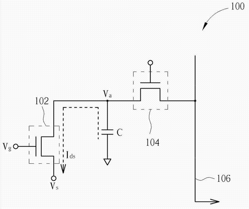
[0004] However, in addition to the sensing unit 100, the photosensitive touch display panel also has pixels for display, and while driving the pixels, it may cause coupling effects on the signal of the sensing unit 100

Method used


Image

  • Touch control display panel and driving method thereof
  • Touch control display panel and driving method thereof
  • Touch control display panel and driving method thereof

Examples


Embodiment Construction

[0043] The present disclosure is particularly described in terms of the following examples, and the use of examples anywhere throughout the specification and drawings, including any use of the wording examples discussed herein, is for illustration only because it would be obvious to those skilled in the relevant art , without departing from the spirit and scope of the disclosure, various changes and modifications can be made, so the protection scope of the disclosure should be defined by the appended claims.

[0044]Those who are familiar with the related art should know that the embodiments of the present invention and its components include other purposes, advantages or characteristics described in the specification, but not explicitly stated, but the embodiments of the present invention essentially have the purpose, advantage or feature. Therefore, the purposes, advantages or features enumerated in the entire specification are not intended to limit the patented invention. ...


PUM


Abstract

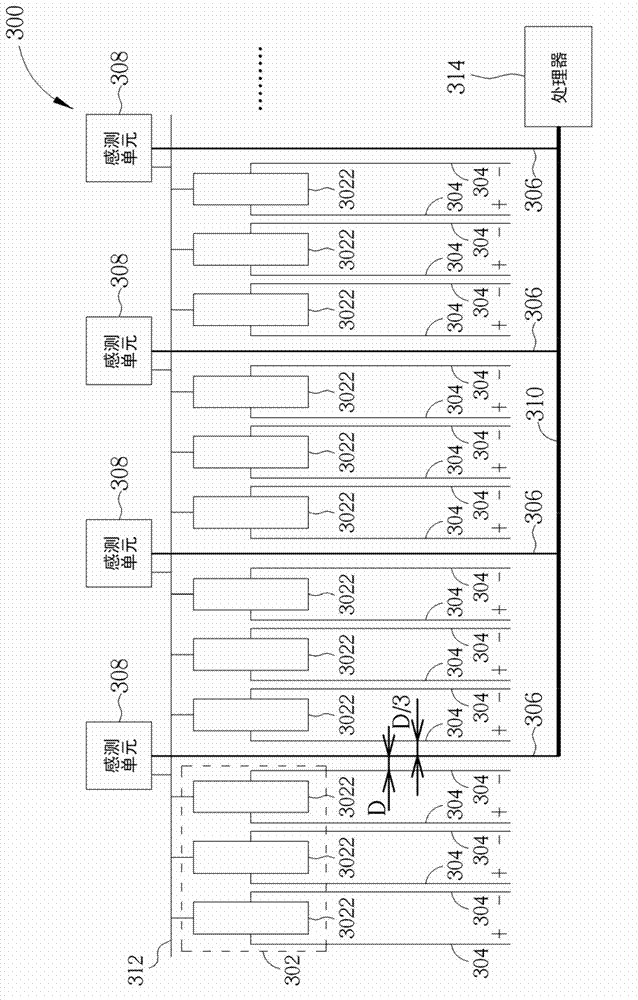
The invention provides a touch control display panel which includes 2N touch control reading lines, 2N sensing units, a touch control induction line, multiple pixels and 2N data lines. a distance between each data line and a corresponding touch control reading line is a first preset value. N data lines of the 2N data lines are used for providing positive-electrode data voltages, and the rest N data lines are used for providing negative-electrode data voltages.

Description

technical field [0001] The present invention relates to a touch display panel and a driving method thereof, in particular to a touch display panel with data lines and a driving method thereof. Background technique [0002] In recent years, the touch display panel has become a popular product. Using the touch display panel as a user operation interface allows users to directly operate electronic products through touch mode instead of keyboard or mouse. The touch display panel will locate the position touched by the user through signal processing according to the change of the sensing signal corresponding to the touch sensing unit. [0003] Please refer to figure 1 . figure 1 It is a schematic diagram of the sensing unit 100 of the photosensitive touch display panel. The sensing unit 100 includes a photosensitive thin film transistor (photo TFT) 102 , a touch readout thin film transistor (readout TFT) 104 and a capacitor C. The photosensitive thin film transistor 102 will ...

Claims


Application Information

Patent Timeline
IPC IPC(8): G06F3/041
Inventor 郑宜如钟岳宏徐雅玲黄雪瑛
Owner AU OPTRONICS CORP
Why Eureka
Try Eureka