Light emitting device and backlight device

一种发光装置、发光元件的技术,应用在照明装置、照明装置的零部件、照明装置的防损措施等方向,能够解决壳体部件104裂纹、碰撞等问题,达到降低断线不良、降低发生概率、光效率良好的效果

Inactive Publication Date: 2014-11-26
SHARP KK
View PDF11 Cites 3 Cited by
  • Summary
  • Abstract
  • Description
  • Claims
  • Application Information

AI Technical Summary

Problems solved by technology

[0010] However, if Figure 10A As shown, when the light-emitting device 100 is brought close to contact with the light guide 106, if the light-emitting element 102 lights up or the surrounding temperature rises, as shown in FIG. Figure 10B As shown, the light guide 106 thermally expands as shown by the arrow, so that the light guide 106 may collide with the light emitting device 100
[0011] Moreover, when the end surface 106a of the light guide body 106 collides with the casing member 104 of the light emitting device 100, if the strength of the casing member 104 is small, as Figure 11 As shown, there is a problem that a crack C is generated in the case member 104
In addition, thereby sealing resin 103 inside ( Figure 6B shown) lead 105 may also be cut

Method used


Image

  • Light emitting device and backlight device
  • Light emitting device and backlight device
  • Light emitting device and backlight device

Examples


no. 1 Embodiment approach

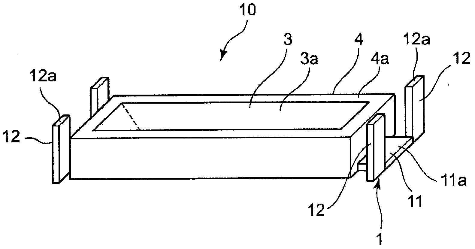
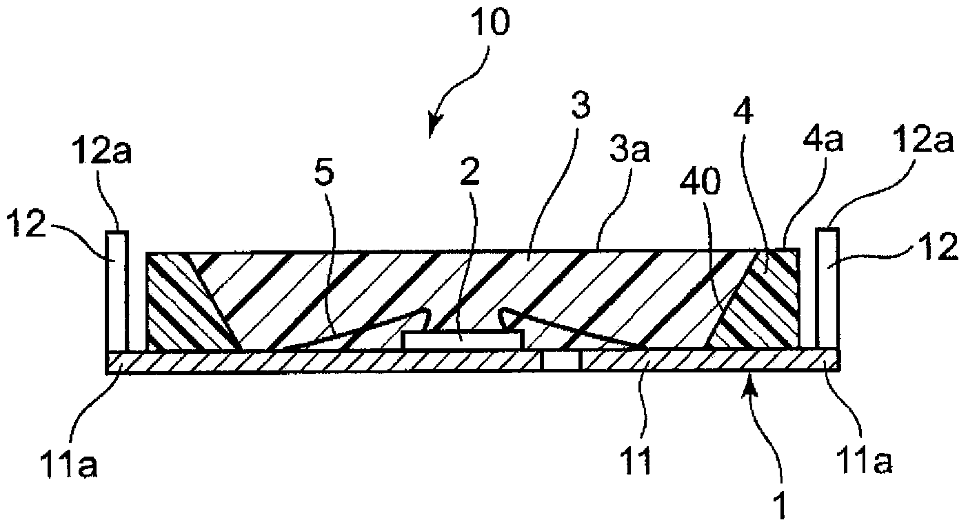
[0060] Figure 1A It is a perspective view showing the light emitting device of the first embodiment of the present invention. Figure 1B It is a cross-sectional view of the light-emitting device. Such as Figure 1A with Figure 1B As shown, the light-emitting device 10 has a lead frame 1, a housing member 4, a light-emitting element 2, and a sealing resin 3.

[0061] The above-mentioned lead frame 1 is made of metal, and has a lead frame main body 11 and a bumper portion 12 standing up from the lead frame main body 11.

[0062] The case member 4 is made of resin, and the bottom surface of the case member 4 is attached to the lead frame main body 11. For example, the case member 4 is formed together with the lead frame 1 by insert molding.

[0063] The housing member 4 has a hole 40. The light-emitting element 2 is arranged in the hole 40. The inner surface of the hole portion 40 is formed as an inclined surface such that the opening side of the hole portion 40 is widened, and the...

no. 2 Embodiment approach

[0083] Figure 4A It is a perspective view showing a light emitting device according to the second embodiment of the present invention. Figure 4B It is a cross-sectional view of the light-emitting device. The difference from the first embodiment described above is described. In the second embodiment, the position where the buffer portion of the lead frame is provided is different.

[0084] In addition, in this second embodiment, the same reference numerals as those of the first embodiment described above are the same configurations as those of the first embodiment described above, and therefore the description thereof is omitted.

[0085] Such as Figure 4A with Figure 4B As shown, in the lead frame 1A of the light-emitting device 10A of the second embodiment, the lead frame main body 11A has a terminal portion 11 a that protrudes from the end in the plane direction and is exposed from the housing member 4. The lead frame main body 11A is formed in a rectangular shape. Terminal ...

no. 3 Embodiment approach

[0093] Figure 5A It is a perspective view showing a light emitting device according to a third embodiment of the present invention. Figure 5B It is a cross-sectional view of the light-emitting device. The difference from the first embodiment described above is described. In the third embodiment, the position where the buffer portion of the lead frame is provided is different.

[0094] In addition, in this third embodiment, since the same reference numerals as in the above-mentioned first embodiment are the same structures as those in the above-mentioned first embodiment, the description thereof is omitted.

[0095] Such as Figure 5A with Figure 5B As shown, in the lead frame 1B of the light-emitting device 10B of the third embodiment, the lead frame main body 11B has a terminal portion 11 a that protrudes from the end in the plane direction and is exposed from the housing member 4. The lead frame main body 11B is formed in a rectangular shape. A pair of opposing sides of the...


PUM


Abstract

The tip surface (12a) of a bumper section (12) is higher than the upper end surface (4a) of a case member (4). Thereby, even if a light guide body (106) collides with a light emitting device (10) due to thermal expansion, the bumper section (12) comes into contact with the light guide body (106) and receives the force from the light guide body (106). As a result, the force from the light guide body (106) is prevented from being transferred to the case member (4). Accordingly, the amount of light flux incident to the light guide body (106) can be increased and the probability of breaking of a wire due to the thermal expansion of the light guide body (106) can be reduced.

Description

Technical field [0001] The present invention relates to a light emitting device and a backlight device. Background technique [0002] In the past, as light-emitting devices, there were Figure 6A with Figure 6B A light-emitting device as shown (see Japanese Patent Application Laid-Open No. 2011-34674: Patent Document 1). [0003] Such as Figure 6A with Figure 6B As shown, the light-emitting device 100 includes a lead frame 101, a light-emitting element 102 arranged on the lead frame 101, a sealing resin 103 arranged on the lead frame 101 and sealing the light-emitting element 102, and a side surface of the sealing resin 103. The surrounding resin case member 104. The lead frame 101 and the light emitting element 102 are connected by the lead 105. The upper end surface 103a of the sealing resin 103 serves as an opening through which the light of the light emitting element 102 is emitted. [0004] The above-mentioned light emitting device 100 such as Figure 7 As described, it is u...

Claims


Application Information

Patent Timeline
Patent Type & Authority Applications(China)
IPC IPC(8): H01L33/62F21S2/00F21Y101/02
CPCG02B6/0023H01L2224/48091G02B6/0073H01L2224/48247H01L33/52H01L33/62H01L2924/00014F21V15/01F21V19/002G02B6/009
Inventor 加藤正明近藤正树
Owner SHARP KK
Why Eureka
Try Eureka