Tool head for use in machine tools

A combination and cutter head technology, which is applied in the direction of milling machine equipment, toolholder accessories, manufacturing tools, etc., can solve the problems of wear and adjustment gaps, etc.

Active Publication Date: 2013-05-08
KOMET GROUP GMBH
View PDF10 Cites 4 Cited by
  • Summary
  • Abstract
  • Description
  • Claims
  • Application Information

AI Technical Summary

Problems solved by technology

This causes wear and undesired adjustment play when combined cutterheads are subjected to high loads during the long-term machining of workpieces with tools

Method used


Image

  • Tool head for use in machine tools
  • Tool head for use in machine tools
  • Tool head for use in machine tools

Examples


Embodiment Construction

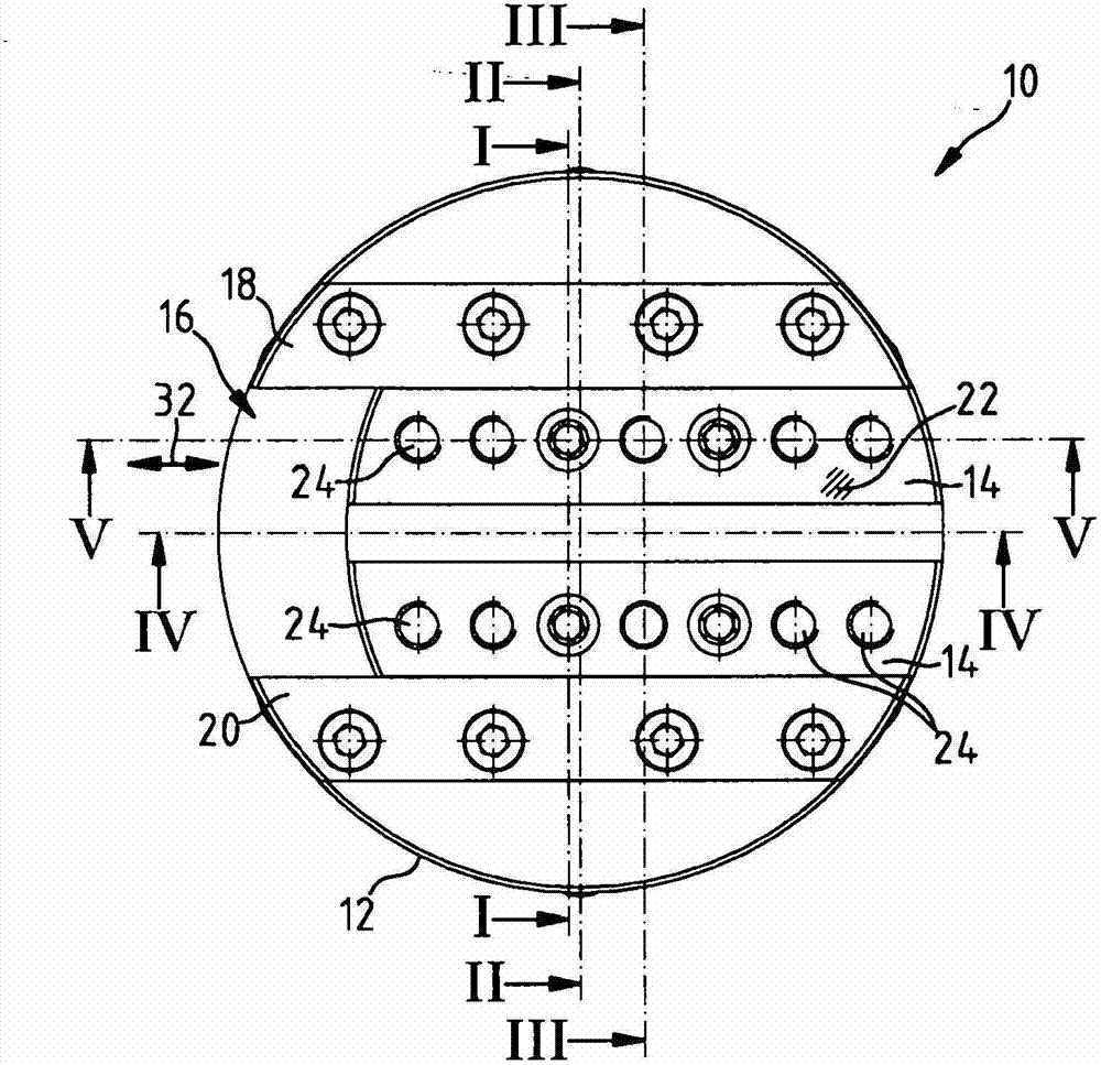
[0024] figure 1 The combined cutter head 10 shown in has a base body 12 . A movable slide 14 is mounted on the base body 12 . The carriage 14 is guided linearly movable in a sliding bearing 16 formed on the base body 12 . The carriage 14 is held in the slide bearing 16 by means of a first web 18 and by means of a second web 20 .

[0025] The slide 14 has a slide working surface 22 which can hold a tool holder for a cutting tool. For connection to the tool holder, a plurality of threaded holes 24 for receiving fastening screws are provided on the slide 14 .

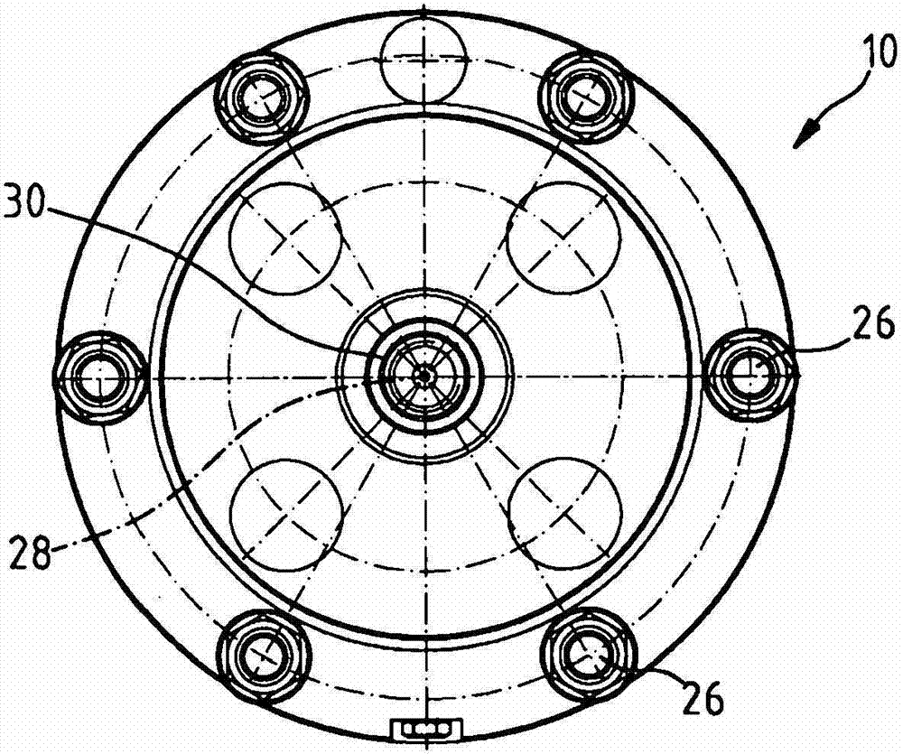
[0026] figure 2 Shown is the back of the modular cutter head 10 . A connecting element 26 is arranged on the rear side of the combination cutter head 10 . By means of a connecting element 26 , the combination cutterhead 10 can be connected to a rotating machine spindle of a machine tool, not further shown. On the machine spindle of the machine tool, the combined cutter head 10 can be rotated at a high rotational sp...


PUM


Abstract

The invention relates to a tool head (10) for use in machine tools, comprising a main body (12) which can be rotated around an axis of rotation (28). The tool head (10) has a slide (14). The slide (14) can be moved by means of a pull rod (30) axially oriented in the main body (12). The slide (14) can be fitted with at least one tool or one tool holder. At least one adjustable toothed plate (36, 38) is fixedly arranged on the slide (14). The toothed plate (36, 38) comprises a helical gearing (42, 44) functioning as a gear means for engaging with a helical gearing (44, 48) of the pull rod (30) which is complementary thereto. According to the invention, the slide (14) has an adjustment unit (66) for moving the at least one toothed plate (36, 38) and the helical gearing (42, 44) thereof into the complementary helical gearing (44, 48) of the pull rod (30).

Description

technical field [0001] The invention relates to a combined cutterhead for use in machine tools, comprising a base body rotatable about an axis of rotation and a slide movable by means of an axially oriented tie rod in the base body, the slide being able to hold at least one tool Or a knife holder, wherein at least one adjustable toothed rack is fastened to the carriage, the toothed rack having helical teeth acting as a transmission element for meshing with the complementary helical teeth of the pull rod. Background technique [0002] Combined cutterheads of this type are used in machine tools for machining structural elements such as slots, relief backs, journals and bores. In principle, two or more slides can also be provided on the combined cutter head. [0003] Such a combined cutter head is described in DE 43 14 295 A1. The combined cutter head has a base body which rotates about a rotational axis. Combination cutterheads consist of a slide. The slide serves as a rec...

Claims


Application Information

Patent Timeline
Patent Type & Authority Applications(China)
IPC IPC(8): B23B29/034
CPCB23B29/0345B23C2260/04B23B29/034Y10T82/12Y10T408/858957Y10T82/125Y10T408/85895Y10T408/8588B23B29/03425
Inventor R·维斯特A·安东尼F·施塔德勒
Owner KOMET GROUP GMBH
Why Eureka
Try Eureka