Coupling device for seismic sensors

a technology of coupling device and seismic sensor, which is applied in the field of geophysical, can solve the problems of unsatisfactory solution, inability to meet the requirements of the application, and inability to meet the requirements of the application, and achieve the effect of preserving the physical integrity of the sensor

Inactive Publication Date: 2016-11-15
SERCEL INC
View PDF12 Cites 2 Cited by
  • Summary
  • Abstract
  • Description
  • Claims
  • Application Information

AI Technical Summary

Benefits of technology

[0012]The coupling device according to the invention is remarkable in that it enables to solve two problems simultaneously. The supporting portion will maintain the sensor unit in a stable position when resting on or buried into the ground, while the rod or rods linked to the supporting portion will provide an additional stiffness to the sensor unit's housing, and thus suppress resonating frequencies which would be generated by a housing.
[0014]Such a symmetric shape allows a homogeneous mass distribution in the horizontal plane when the coupling device is placed on or buried into the ground, which will thus contribute to prevent the coupling device from vibrating in operating conditions.
[0018]Multiple rods will increase the stiffening effect produced by the coupling device, which effect will be yet again magnified by the fins. A further reason for using a combination of rods and fins instead of a plain shape like a cylinder lies in the spaces separating said fins and rods, which allow loose soil (like sand for example) to flow within the space delimited by the external surface of the coupling device. The filling of this space will simultaneously produce a double advantage, since it will help anchor the coupling device on or even within the ground, and it will allow direct contact between the ground and the housing, which will enhance the performance of the sensor.
[0020]According to a specific embodiment, the first supporting portion is provided with a groove supporting an O-ring and intended to be located between the coupling device and the housing. In this embodiment, the O-ring will compensate any clearance between the third supporting portion and the end of the housing, thus ensuring that the housing and the coupling device are firmly fastened to each other. Since the third supporting portion is arranged between the first and second supporting portions, the end of the housing is located well within the coupling device when the housing is fastened to it, which will help to protect the sensor's integrity in case of an impact between the second supporting portion and the ground.
[0026]The physical properties of a coupling device inherent to such a symmetric shape impart to the assembly formed by the sensor unit and the coupling device an optimal resistance to resonance effects.

Problems solved by technology

Such a solution is not entirely satisfactory.
It has proven impractical in applications where the ground is too hard for a spike to be buried into it, as is the case on urban premises.
In such a situation, the sensor unit will have to be simply laid down on the ground and will thus be very unstable, the end result being that the measurements it will take will probably be inaccurate.
For similar reasons, the known solution is impractical when used in arctic conditions.
Specially adapted spikes have been designed for such conditions, but these special spikes are very heavy and therefore are detrimental to operational efficiency.
Furthermore, a spike-shaped coupling device may be insufficiently effective to ensure sensor stability in loose soil, e.g. when the ground is made of sand or mud, in which case the spike won't be maintained in position as well as it would be in a more dense, and thus less shifting, environment.
In order to solve this stability problem, additional pedestals in the form of tripods or quadripods are sometimes used, but such pedestals have a tendency to resonate on their own modes and produce non-desired resonant frequencies, which is detrimental to the operational efficiency of the sensor.
These non-desired resonant frequencies (noise) would pollute the measured data consequently especially if said sensor is a digital seismic sensor because of their high sensitivity to noise.
However, this design presents a drawback due to the elongated shape of the pod protruding from the housing's bottom, which will tend to resonate at a frequency comprised within the bandwidth under study and may thus significantly alter the operational performance of the sensor unit.

Method used


Image

  • Coupling device for seismic sensors
  • Coupling device for seismic sensors
  • Coupling device for seismic sensors

Examples


Embodiment Construction

5.1 General Principle

[0037]The coupling device according to an embodiment of the invention is remarkable in that it enables to solve two problems simultaneously, by means of at least one supporting portion which will maintain the sensor unit in a stable position when resting on or buried into the ground, while a rod or rods linking both supporting portions will provide an additional stiffness to the sensor unit's housing.

5.2 Description of a Specific Embodiment

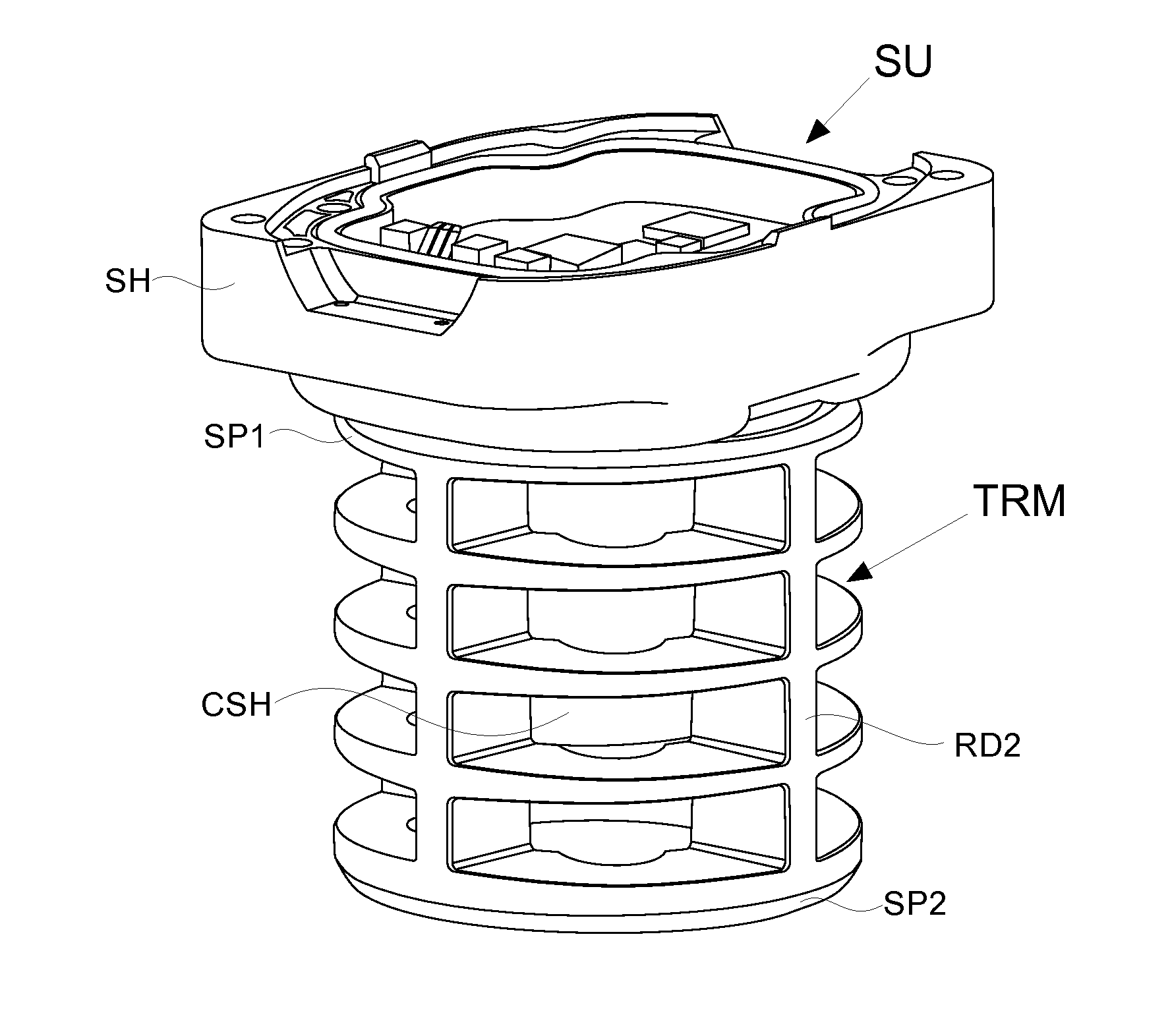
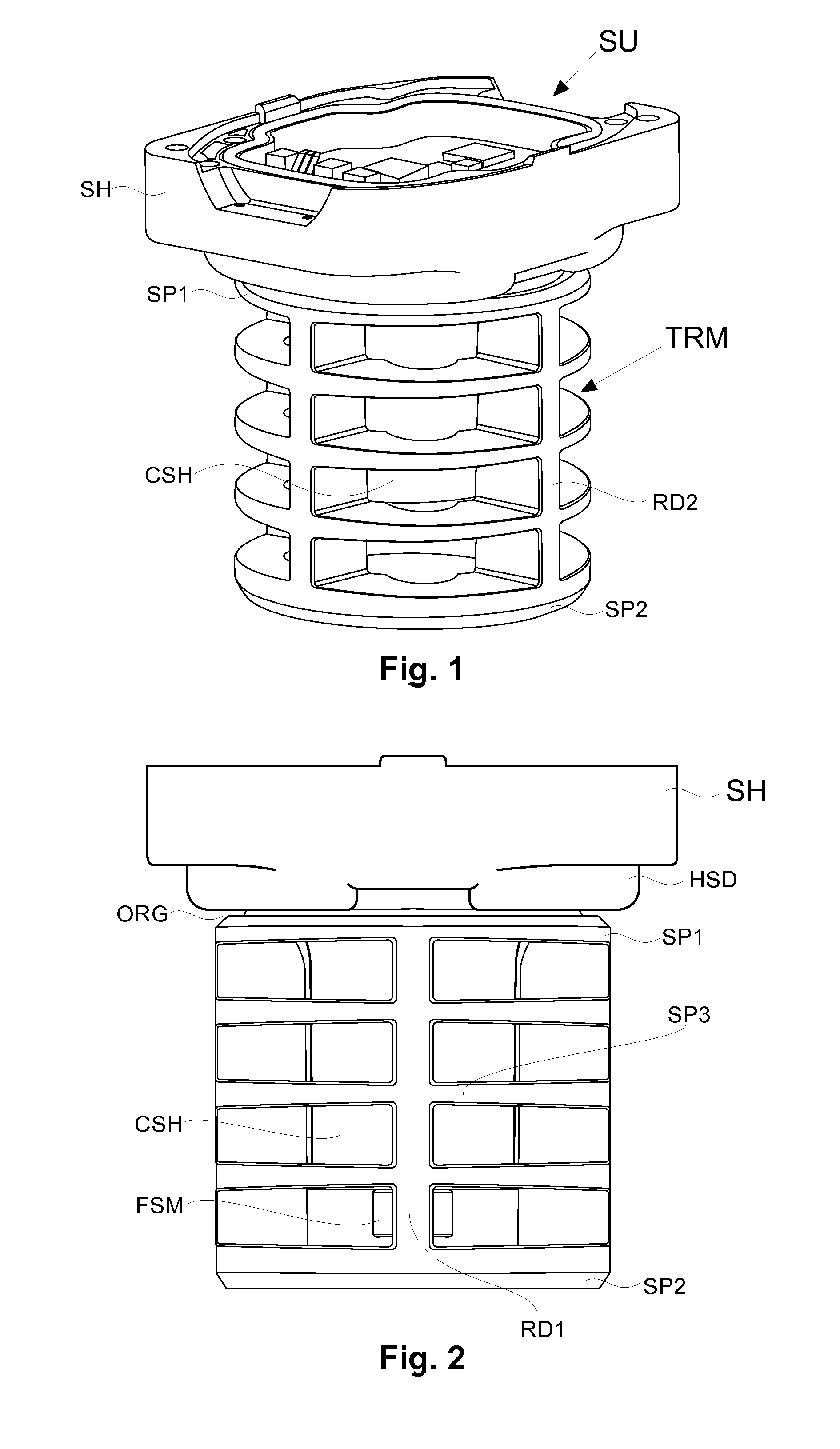
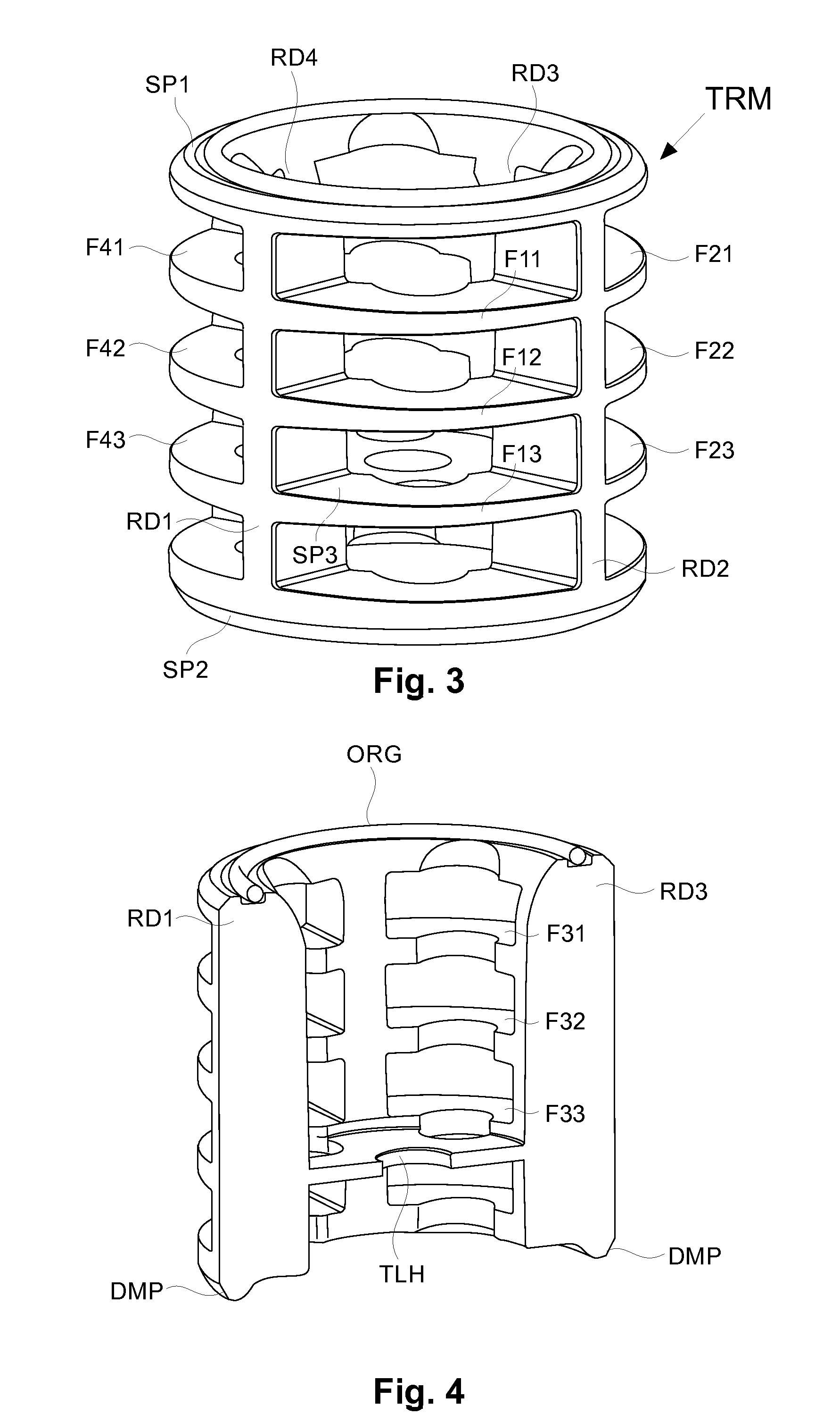
[0038]FIG. 1 and FIG. 2 disclose a coupling device TRM for a sensor unit SU comprising at least one sensor located within a housing SH, which coupling device TRM includes in this embodiment four rods of which only a first and a second rods RD1 and RD2 are shown here.

[0039]The sensor may be a one vertical component digital sensor or a three orthogonal component digital sensor like a geophone or an accelerometer.

[0040]The coupling device TRM features a first supporting portion SP1 featuring a groove supporting an O-ring ORG agai...


PUM


Abstract

A coupling device is provided for a sensor unit having at least one sensor located within a housing. The coupling device includes at least one supporting portion, wherein the supporting portion is configured for maintaining the sensor unit in a stable position, with the coupling device either resting on or being buried into the ground, and at least one rod, arranged in a plane which is essentially perpendicular to a peripheral surface of the supporting portion and linked to the supporting portion. The coupling device further includes a fastener for connecting the sensor unit to the coupling device. The supporting portion maintains the sensor unit in a stable position when resting on the ground, while the rod provides an additional stiffness to the housing.

Description

1. FIELD OF THE INVENTION[0001]The invention pertains to the geophysical domain, and relates to applications in which sensor units are used to map subterranean properties of a given geographical area.[0002]More specifically, the invention relates to coupling devices for such sensor units enabling to position the sensor units on the surface of said geographical area.[0003]Although the invention may be used in various applications involving acquisition of seismic data through a network of sensor units, it is of particular interest to the oil prospection industry.2. BACKGROUND OF THE INVENTION[0004]In the known state of the art, seismic data are collected by networks of electronic sensor units, which are connected to a central processing server.[0005]Each sensor unit comprises at least one sensor located within a housing, which features a bottom surface intended to be mechanically coupled with the ground. To this end, a sensor unit is usually equipped with a coupling device having the ...

Claims


Application Information

Patent Timeline
Patent Type & Authority Patents(United States)
IPC IPC(8): G01D11/30G01V1/16F16B17/00G01S7/521
CPCG01D11/30F16B17/00G01S7/521G01V1/16Y10T403/52Y10T403/70F16B2200/60G01V1/181G01V1/166
Inventor PICHOT, YANN
Owner SERCEL INC
Why Eureka
Try Eureka