Cooling system for a dynamoelectric machine
- Summary
- Abstract
- Description
- Claims
- Application Information
AI Technical Summary
Benefits of technology
Problems solved by technology
Method used
Image
Examples
Embodiment Construction
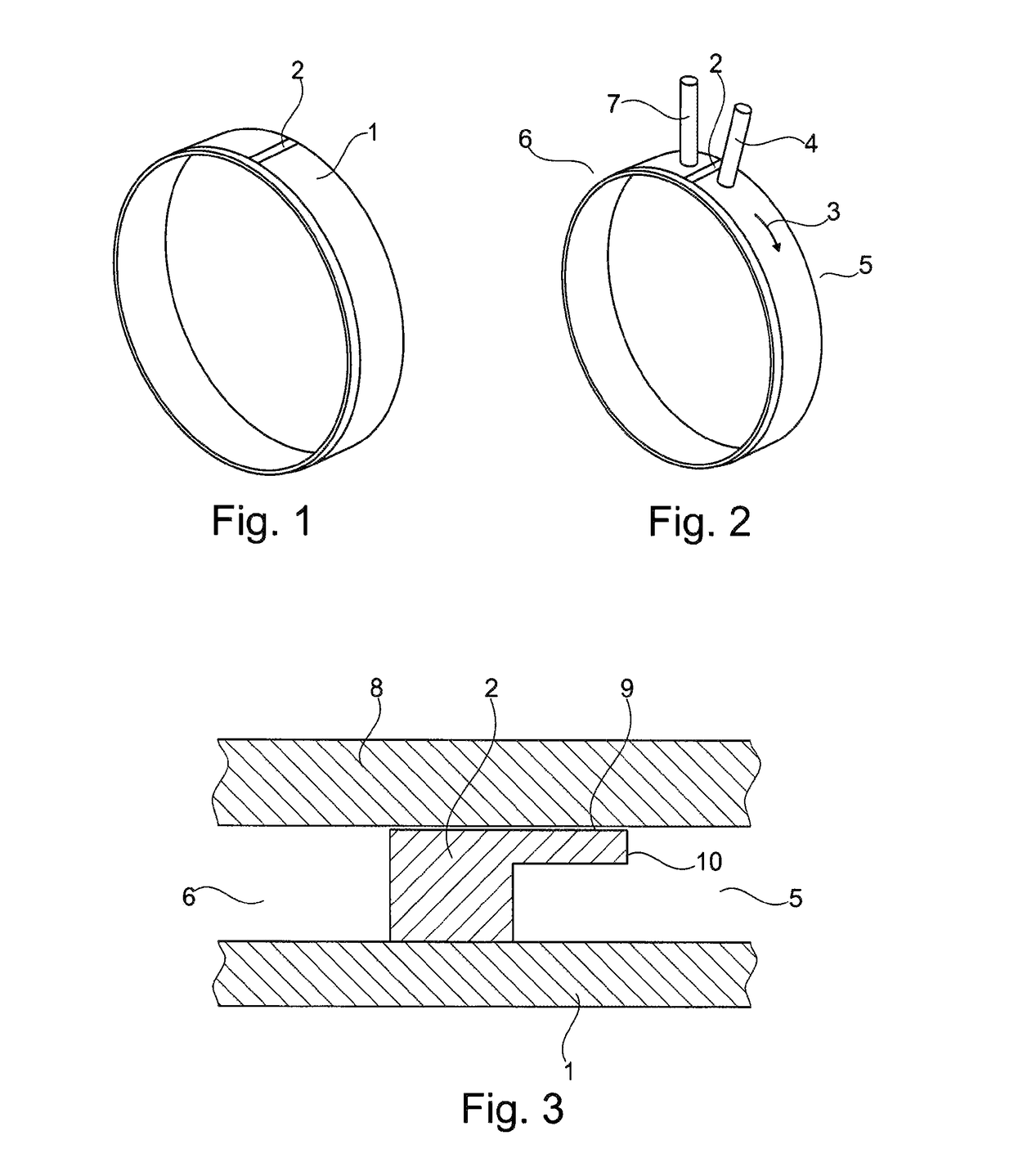
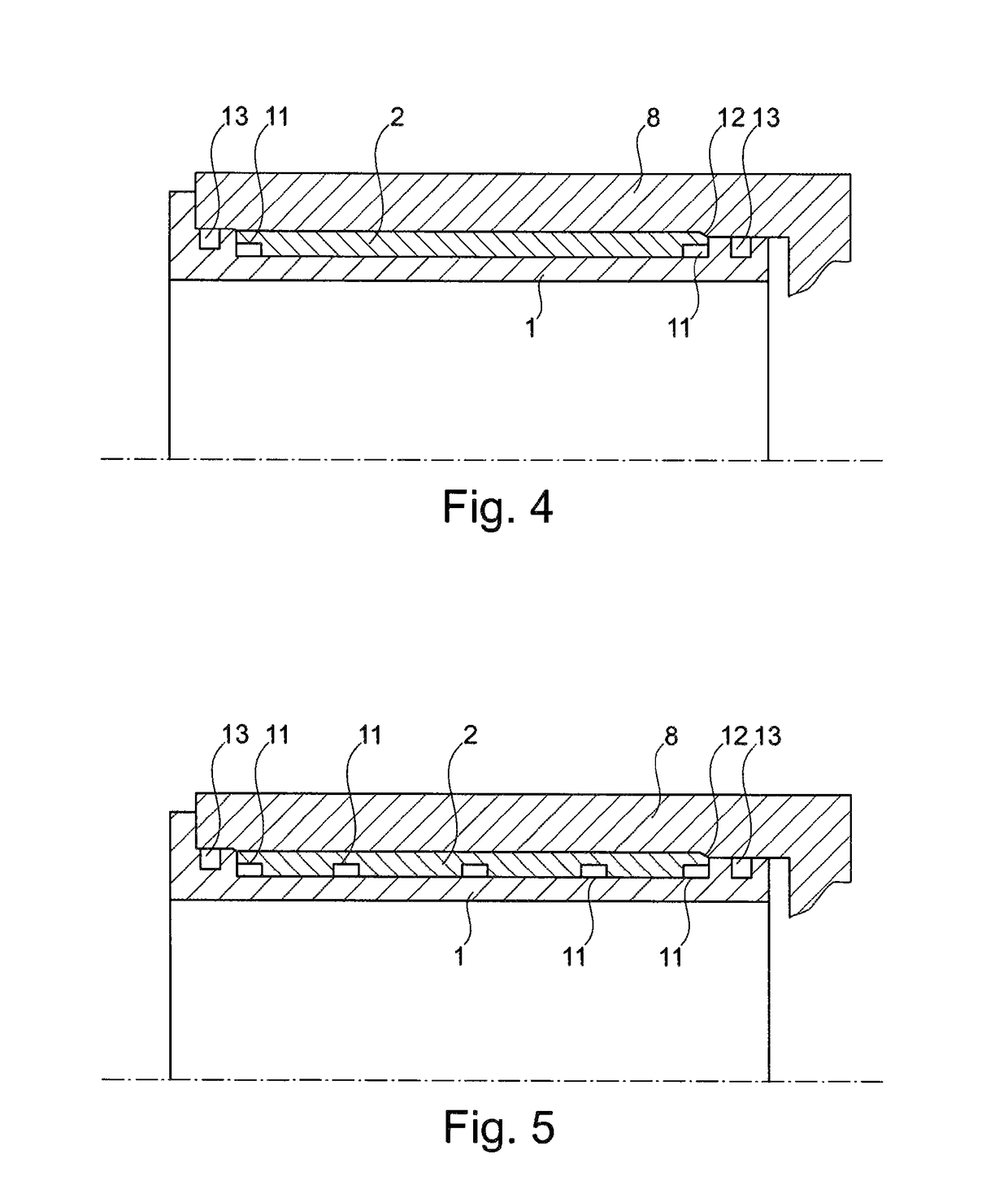
[0029]FIG. 1 shows a cooling jacket 1 including a barrier element 2 according to one embodiment of the present invention. FIG. 2 shows a coolant flow 3, which, in one specific embodiment of the present invention, is essentially oriented in the circumferential direction of a stator of an electric machine. The coolant flow is delimited radially on the inside by the outer wall of cooling jacket 1 and radially on the outside by the inner wall of a housing, which surrounds cooling jacket 1 and is not illustrated here. The coolant is first admitted into an inlet area 5 of the cavity through an inlet opening 4, which is illustrated only schematically here. Coolant flow 3 now flows from inlet area 5 along the circumference of the electric machine without reversing direction to outlet area 6, from where it flows out of the cavity through outlet opening 7. Between inlet opening 4 and outlet opening 7, barrier element 2 prevents coolant flow 3 from flowing from inlet opening 4 to outlet openin...
PUM
 Abstract
Description
Claims
Application Information
 - R&D
- Intellectual Property
- Life Sciences
- Materials
- Tech Scout
- Unparalleled Data Quality
- Higher Quality Content
- 60% Fewer Hallucinations
Browse by: Latest US Patents, China's latest patents, Technical Efficacy Thesaurus, Application Domain, Technology Topic, Popular Technical Reports.
© 2025 PatSnap. All rights reserved.Legal|Privacy policy|Modern Slavery Act Transparency Statement|Sitemap|About US| Contact US: help@patsnap.com


