Cooling system for a dynamoelectric machine

Active Publication Date: 2016-06-16
SCHAEFFLER TECH AG & CO KG
View PDF10 Cites 8 Cited by
  • Summary
  • Abstract
  • Description
  • Claims
  • Application Information

AI Technical Summary

Benefits of technology

[0022]In one advantageous embodiment of the present invention, a chamfer on the barrier element on at least one front side of the cooling jacket assists with the insertion of the stator provided with the cooling jacket into the housing,

Problems solved by technology

As a result, the stator provided with the cooling jacket may form an interference fit together with the housing at room temperature, but this interference fit transitions to a clearance fit as the temperature rises during operation of the electric machine.

Method used


Image

  • Cooling system for a dynamoelectric machine
  • Cooling system for a dynamoelectric machine
  • Cooling system for a dynamoelectric machine

Examples


Embodiment Construction

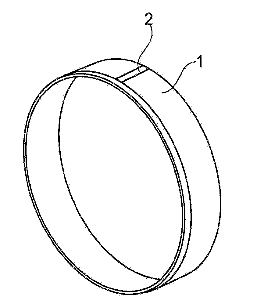
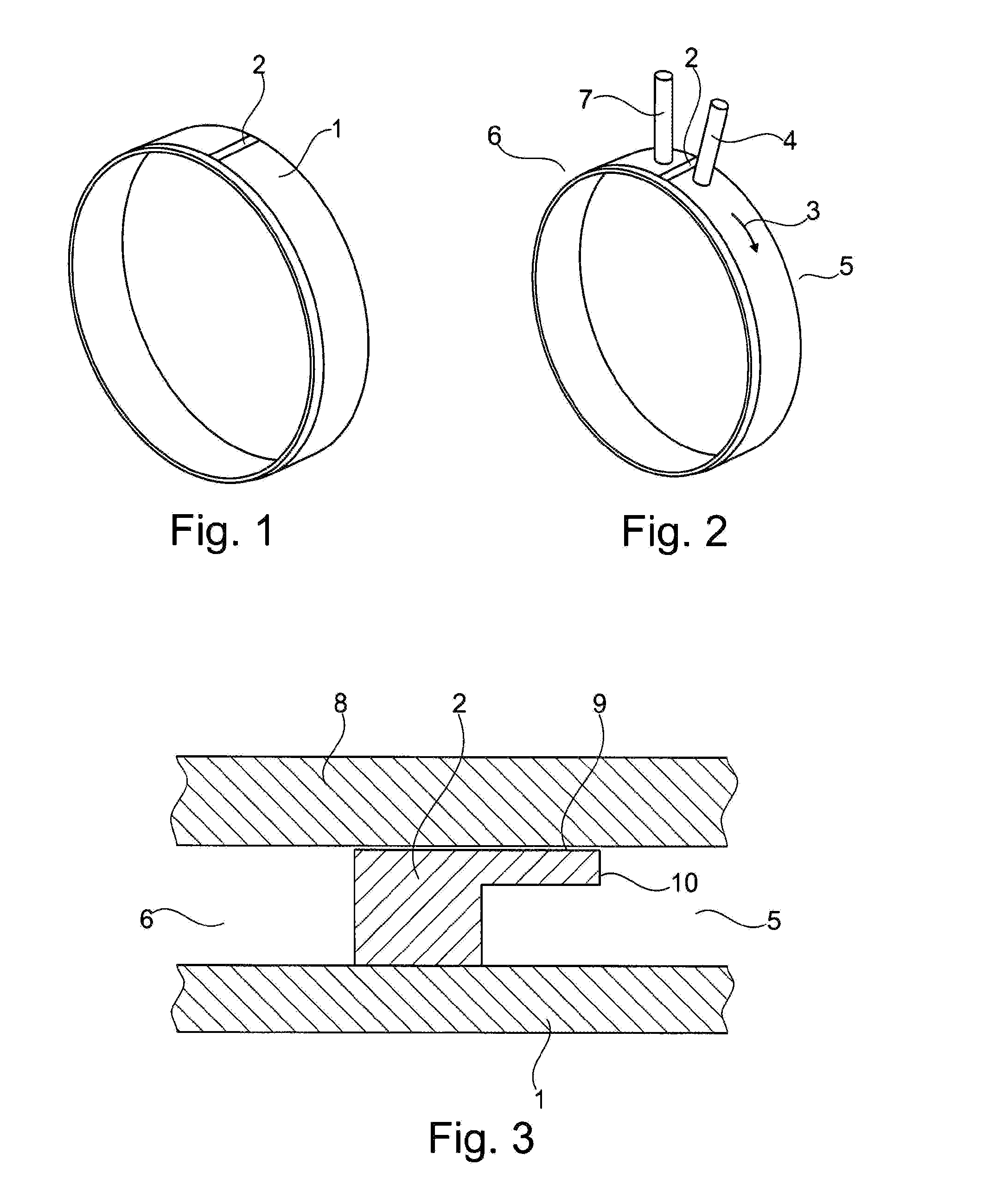
[0029]FIG. 1 shows a cooling jacket 1 including a barrier element 2 according to one embodiment of the present invention. FIG. 2 shows a coolant flow 3, which, in one specific embodiment of the present invention, is essentially oriented in the circumferential direction of a stator of an electric machine. The coolant flow is delimited radially on the inside by the outer wall of cooling jacket 1 and radially on the outside by the inner wall of a housing, which surrounds cooling jacket 1 and is not illustrated here. The coolant is first admitted into an inlet area 5 of the cavity through an inlet opening 4, which is illustrated only schematically here. Coolant flow 3 now flows from inlet area 5 along the circumference of the electric machine without reversing direction to outlet area 6, from where it flows out of the cavity through outlet opening 7. Between inlet opening 4 and outlet opening 7, barrier element 2 prevents coolant flow 3 from flowing from inlet opening 4 to outlet openin...


PUM


Abstract

A cooling system for a dynamoelectric machine comprising a cooling jacket for assembly on an outer circumference of a stator of the dynamoelectric machine, a housing for receiving the stator having the mounted cooling jacket such that a hollow chamber, which can be filled with a liquid cooling medium, remains between an outer wall of the cooling jacket and an inner wall of the housing, wherein an inlet opening for inlet of the cooling medium into an inlet region and an outlet opening for outlet of the cooling medium from an outlet region of the hollow chamber are arranged on the housing and a barrier element connected to the cooling jacket for spatial separation of the inlet region from the outlet region is provided. The efficiency of such a cooling system is improved in that the barrier element presses against the inner wall of the housing having increasing pressure difference of the cooling medium in the inlet and outlet region.

Description

[0001]The present invention relates to a cooling system for a dynamoelectric machine. The present invention also relates to a dynamoelectric machine which includes a cooling system of this type.BACKGROUND[0002]Particularly when the objective is a compact design and a high energy density of an electric drive associated therewith, liquid cooling is generally used to cool dynamoelectric machines. A typical area of application, in which the compact design of an electric drive plays a particularly large role, is electromobility. Due to the limited installation space in the motor vehicle, the objective is a particularly high power density of the traction machine used for the drive.[0003]An electric machine which includes a liquid cooling system is thus known from DE102008014386A1, which has the features according to the definition of the species in Patent claim 1. To cool the stator, a cooling jacket is mounted on its outer circumference. A housing for accommodating the stator, including ...

Claims


Application Information

Patent Timeline
Patent Type & Authority Applications(United States)
IPC IPC(8): H02K9/19H02K5/20
CPCH02K5/20H02K9/19H02K1/20H02K5/203
Inventor WEIS, JOHANNESSCHAEFER, CHRISTIANMACKOWIAK, STEFANHEITZ, SEBASTIAN
Owner SCHAEFFLER TECH AG & CO KG
Why Eureka
Try Eureka