Centrifugal barrel rotation coaxiality detection mechanism

A detection mechanism and centrifugal bucket technology, applied in measuring devices, instruments, optical devices, etc., can solve the problems of inability to realize real-time rotation detection, wear of sliding distance sensors, and difficulty in centering for eccentricity detection, and achieve small matching clearance, The effect of compensating the gap and reducing the difficulty of installation

Active Publication Date: 2021-01-15
JIANGSU WANFENG MARINE EQUIP MFG
View PDF7 Cites 2 Cited by
  • Summary
  • Abstract
  • Description
  • Claims
  • Application Information

AI Technical Summary

Problems solved by technology

[0002] The centrifugal barrel is connected to the rotating shaft with a large-size rotating bearing. After long-term use, the rotation will be unstable or even jump due to the wear of the barrel wall and the deformation of the rotating shaft. At this time, the centrifugal barrel needs to be corrected. If it is not corrected, the running jitter will increase, which will easily lead to equipment failure, so it is necessary to correct and detect the positioning; the traditional eccentricity detection is difficult to center, and it can only be detected by directly contacting the wall of the centrifuge barrel through the position sensor, because the barrel wall High-speed rotation will bring errors to the optical distance sensor and wear to the sliding distance sensor. It can only be detected by stepping, and it cannot realize real-time rotation for detection.

Method used


Image

  • Centrifugal barrel rotation coaxiality detection mechanism

Examples


Embodiment Construction

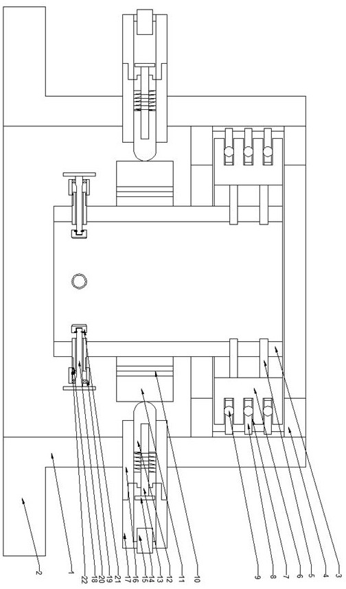
[0025] The present invention is described in further detail now in conjunction with accompanying drawing. These drawings are all simplified schematic diagrams, which only illustrate the basic structure of the present invention in a schematic manner, so they only show the configurations related to the present invention.

[0026] Such as figure 1 As shown, the present invention is a centrifugal barrel rotation coaxiality detection mechanism, including:

[0027] Positioning frame, the top of the positioning frame is connected to a rotating sleeve through a rotating support mechanism, and the middle of the positioning frame is in contact with the rotating sleeve through a pendulum detection mechanism;

[0028] The rotating support mechanism includes a supporting inner ring coaxially fixedly connected to the outer wall of the rotating sleeve, a number of annular inlaid grooves are arranged in a linear array on the supporting inner ring, and two sets of limit rings are arranged on ...


PUM


Abstract

The invention relates to a centrifugal barrel rotation coaxiality detection mechanism, which comprises a positioning frame, wherein the top of the positioning frame is connected with a rotating sleevethrough a rotary support mechanism; the rotary supporting mechanism comprises a supporting inner ring coaxially and fixedly connected to the outer wall of a rotary sleeve, a plurality of annular inlaying grooves are formed in the supporting inner ring in a linear array mode, two sets of limiting rings are arranged at the top of the positioning frame, the supporting inner ring is located between the limiting rings, and a plurality of supporting pieces are further arranged at the positions, corresponding to the positions between the limiting rings, of the inner wall of the positioning frame ina linear array mode and embedded into the inlaying grooves; a clamping mechanism, which comprises a plurality of pressing rods which are arranged on the inner wall of the rotary sleeve in an annular array manner; a deflection detecting mechanism, which comprises a floating ring rotationally connected to the outer wall of the rotary sleeve, wherein an indicating mechanism comprises a sliding sleeveperpendicularly connected to the side wall of the positioning frame, a push rod is slidably connected into the sliding sleeve, a relaxation spring is arranged at the tail end of the sliding sleeve, and a displacement sensor is further connected between the tail end of the sliding sleeve and the push rod.

Description

technical field [0001] The invention relates to a detection mechanism for the rotational coaxiality of a centrifuge barrel, which belongs to the field of centrifuge manufacturing equipment. Background technique [0002] The centrifugal barrel is connected to the rotating shaft with a large-size rotating bearing. After long-term use, the rotation will be unstable or even jump due to the wear of the barrel wall and the deformation of the rotating shaft. At this time, the centrifugal barrel needs to be corrected. If it is not corrected, the running jitter will increase, which will easily lead to equipment failure, so it is necessary to correct and detect the positioning; the traditional eccentricity detection is difficult to center, and it can only be detected by directly contacting the wall of the centrifuge barrel through the position sensor, because the barrel wall High-speed rotation will bring errors to the optical distance sensor and wear to the sliding distance sensor. I...

Claims


Application Information

Patent Timeline
Patent Type & Authority Applications(China)
IPC IPC(8): G01B11/27
CPCG01B11/272
Inventor 陆凯莱
Owner JIANGSU WANFENG MARINE EQUIP MFG
Why Eureka
Try Eureka