Lifting location locking device

A locking device, lifting and positioning technology, applied in the directions of transportation and packaging, conveyors, conveyor objects, etc., can solve the problems of high cost, complex structure, low positioning accuracy, etc., achieve low manufacturing cost, wide application range, positioning high precision effect

Active Publication Date: 2015-07-22
MIRACLE AUTOMATION ENG CO LTD
View PDF5 Cites 0 Cited by
  • Summary
  • Abstract
  • Description
  • Claims
  • Application Information

AI Technical Summary

Problems solved by technology

The traditional positioning and locking device is usually clamped by two cylinders, connecting rod stoppers and horizontal push head, which has complex structure, high cost and low positioning accuracy

Method used


Image

  • Lifting location locking device
  • Lifting location locking device
  • Lifting location locking device

Examples


Embodiment Construction

[0013] The present invention will be further described below in conjunction with specific drawings and embodiments.

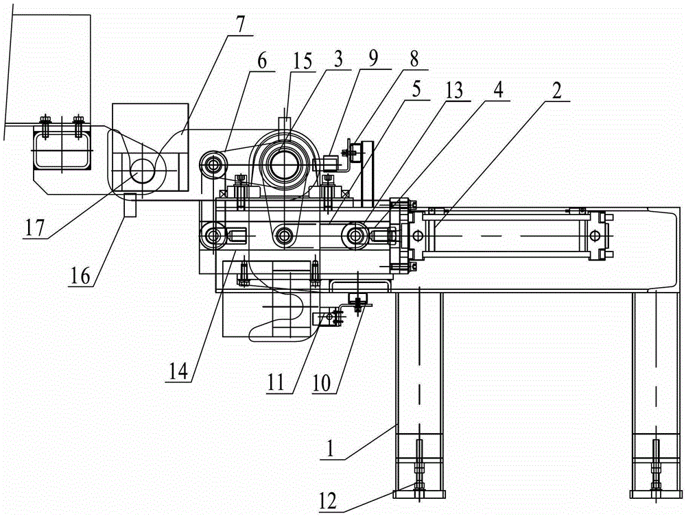
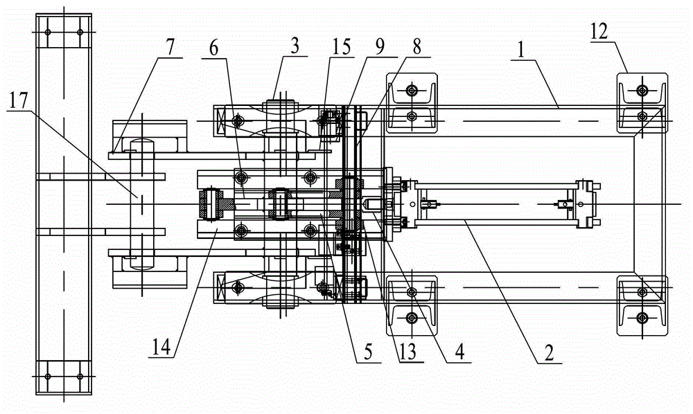
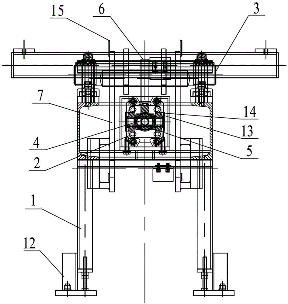
[0014] As shown in the figure: the lifting positioning and locking device in the embodiment is mainly composed of a frame 1, a cylinder 2, a rotating shaft 3, a cylinder joint 4, a connecting rod 5, a swing rod 6, a positioning groove plate 7, an upper bracket 8, and an upper switch 9 , lower bracket 10, lower switch 11, adjusting foot 12, guide wheel 13, guide groove 14, the first number-issuing plate 15 and the second number-issuing plate 16 and other components.

[0015] Such as Figure 1~Figure 3 As shown, the two ends of the rotating shaft 3 are installed in the bearing seat at the top of the frame 1, and the rotating shaft 3 is driven to swing through the rotating drive mechanism; The two ends are provided with positioning and locking grooves. When the rotating shaft 3 rotates, it drives the positioning groove plate 7 to rotate. The positioning and locki...


PUM


Abstract

The invention relates to a lifting location locking device. The lifting location locking device is characterized by comprising a rack, a rotating shaft, a locating groove plate and a rotation driving mechanism, two ends of the rotating shaft are arranged in a bearing seat at the top of the rack, the rotating shaft is driven by the rotation driving mechanism to rotate, a first end of the locating groove plate is fixed on the rotating shaft, a second end of the locating groove plate is provided with a location locking groove, the rotating shaft drives the locating groove plate to rotate at rotating time, and the location locking groove in the locating groove plate is used for being clamped and matched with a locating shaft on a sliding frame roller bed. The lifting location locking device is simple in structure, high in locating precision, wide in application range, low in manufacture cost, and capable of conveniently locating and locking the sliding frame roller bed and enabling transfer loading to be conducted stably.

Description

technical field [0001] The invention relates to a lifting positioning and locking device for positioning and locking a carriage rolling bed when a lift is in place to transfer workpieces, and belongs to the technical field of automobile manufacturing. Background technique [0002] During the production process, the car needs to be transferred to other equipment after being raised or lowered by the elevator. During the transfer process, as the center of gravity of the workpiece moves forward, the carriage rolling bed carrying the workpiece will sink and shake to varying degrees , which requires a device capable of positioning and locking the carriage roll bed, so that the transfer can be carried out smoothly. The traditional positioning and locking device is usually clamped by two cylinders, a connecting rod stopper and a horizontal push head, which has a complex structure, high cost and low positioning accuracy. Contents of the invention [0003] The object of the present...

Claims


Application Information

Patent Timeline
Patent Type & Authority Patents(China)
IPC IPC(8): B65G25/06B65G47/46B65G47/52
Inventor 甘玉戴卫刚
Owner MIRACLE AUTOMATION ENG CO LTD
Why Eureka
Try Eureka