
Electrolytic copper crane sling

A crane, electrolytic copper technology, applied in the direction of load hanging components, transportation and packaging, can solve the problem of frequent and targeted changes in the shape and position of the pole plate lifting lugs

Inactive Publication Date: 2013-05-15
重庆寿丰科技有限公司
View PDF0 Cites 11 Cited by
  • Summary
  • Abstract
  • Description
  • Claims
  • Application Information

AI Technical Summary

Problems solved by technology

[0003] The present invention intends to provide an electrolytic copper crane sling to solve the problem in the prior art that the shape and position of the pole plate lifting lug need to be frequently and targetedly changed

Method used


Image

  • Electrolytic copper crane sling

Examples


Embodiment Construction

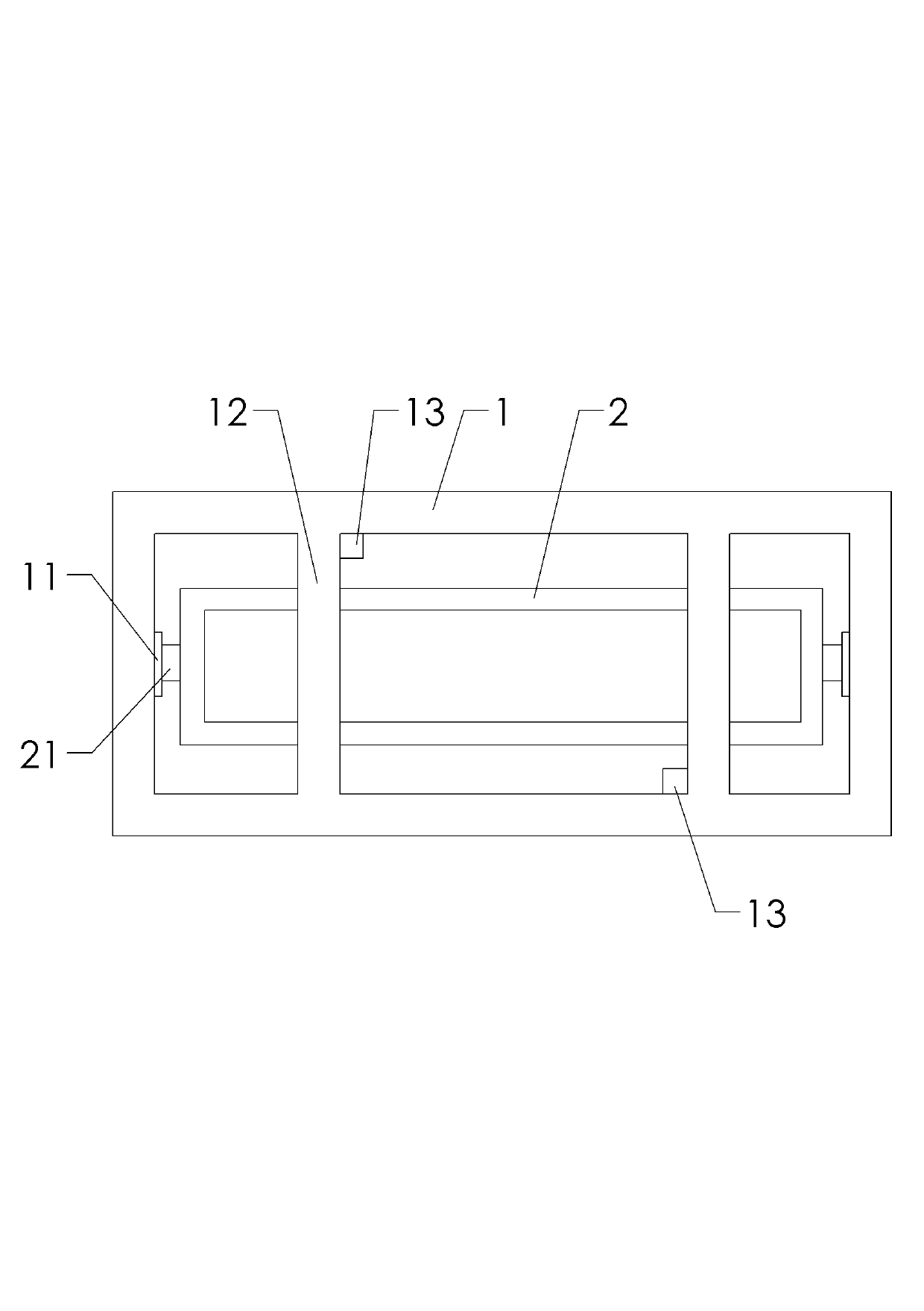
[0012] Such as figure 1 As shown: the electrolytic copper crane hanger in this implementation includes an anode hanger 1 and a cathode hanger 2, and two balance arms 12 are fixedly welded on the anode hanger 1, and the anode hanger 1 and the cathode hanger 2 are rectangular frame structures , the anode hanger 1 is located on the periphery of the cathode hanger 2, and the cathode hanger 2 is connected to the anode hanger 1 through the cathode hanger lifting device. The anode plate and the cathode plate are respectively arranged on the anode hanger and the cathode hanger according to the pole pitch. A camera 13 is also provided beside the two balance arms 12 .

[0013] In this embodiment, the cathode hanger hoisting device includes guide slides 11 fixed at both ends of the anode hanger 1 and guide wheels 21 fixed at both ends of the cathode hanger 2, the guide slides 11 and the guide wheels 21 are movably connected In order to realize the lifting movement of the cathode hanger...


PUM


Abstract

The invention discloses an electrolytic copper crane sling, which aims to solve the problem that the shape and position of polar plate lifting lugs are required to be frequently and pertinently changed in the prior art. According to the technical scheme I, the electrolytic copper crane sling is characterized by comprising an anode hanger, a cathode hanger, a cathode adjustment driving device and a balancing arm, wherein the anode hanger and the cathode hanger respectively have a frame structure; the anode hanger is positioned at the periphery of the cathode hanger; and the cathode hanger is connected with the anode hanger through a cathode hanger lifting device. The electrolytic copper crane sling with the technical scheme has the characteristics that due to a horizontal guide device between the anode hanger and the cathode hanger, a conductive rod of a cathode plate is prevented from interfering with an anode hook in the polar plate lifting process, human assistance is not required, anode and cathode polar plates are sequentially discharged or filled, and the target is lifted, thereby achieving the aim of improving the working efficiency of an electrolytic copper crane.

Description

technical field [0001] The invention relates to a lifting device, in particular to a hoisting sling for cathode and anode plates of electrolytic copper. Background technique [0002] The existing lifting sling for cathode and anode plates of electrolytic copper is suitable for automatic positioning according to the ISA method production process, the lifting mechanism is complicated, and the positioning accuracy is high. The vertical relationship of the boards is demanding and time consuming. Only by changing the shape and position of the plate lugs in a targeted manner can the cathode and anode plates be lifted at the same time. Contents of the invention [0003] The present invention intends to provide an electrolytic copper crane sling to solve the problem in the prior art that the shape and position of the pole plate lifting lug need to be changed frequently and in a targeted manner. [0004] Technical solution 1: The electrolytic copper crane hanger in this solution ...

Claims


Application Information

Patent Timeline
IPC IPC(8): B66C1/10
Inventor 鲁明哲
Owner 重庆寿丰科技有限公司
Learn More