Reinforced concrete pipe for structure of rotatablely excavated pile shell

A technology of reinforced concrete pipes and rotary piles, which is applied in the direction of foundation structure engineering, sheet pile walls, buildings, etc., and can solve problems such as difficulty, installation and transportation

Active Publication Date: 2015-04-01
CHINA METALLURGICAL CONSTR ENG GRP
View PDF6 Cites 0 Cited by
  • Summary
  • Abstract
  • Description
  • Claims
  • Application Information

AI Technical Summary

Problems solved by technology

[0006] Aiming at solving the problems of the overall strength and difficulty in installation and transportation of the reinforced concrete pipe used for the soil accumulation stop device used in the rotary digging pile hole, the invention provides a special steel bar for the rotary digging pile shell structure concrete pipe

Method used


Image

  • Reinforced concrete pipe for structure of rotatablely excavated pile shell
  • Reinforced concrete pipe for structure of rotatablely excavated pile shell
  • Reinforced concrete pipe for structure of rotatablely excavated pile shell

Examples


Embodiment 1

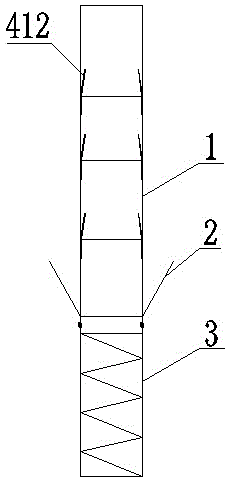
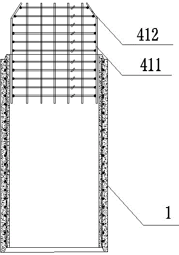
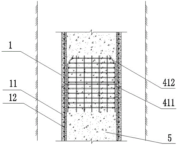
[0022] Embodiment 1: (see figure 2 - image 3 ), a reinforced concrete pipe used for the pile shell structure of rotary excavation piles, including a pipe body 1, the pipe body 1 contains a number of longitudinal bars 11 and a number of stirrup bars 12, and the connecting parts of the two ends or one end of the pipe body 1 A reinforcement connection structure is provided for positioning and connecting two adjacent pipe bodies into an integrated structure. The connecting structure of the steel bar is a socketing method; one end of the pipe body 1 is provided with a convex ring section 411, and the other end of the pipe body 1 is provided with a socket section matched with the convex ring section 411; the convex ring section 411 consists of several vertically arranged main reinforcements and circumferentially arranged stirrups.

[0023] In order to improve the docking operability and facilitate the guided docking, the upper end of the convex ring section 411 is also provided ...

Embodiment 2

[0027] Embodiment 2: (see Figure 4 - Image 6 ), and the difference from Embodiment 1 is that the steel bar connection structure is a butt joint; screw sections 421 and 422 are respectively extended outward along the pipe wall at both ends of the pipe body 1 , and are butt jointed by a sleeve 423 .

[0028] In this embodiment, when two adjacent pipe bodies need to be fastened, the one-to-one corresponding upper and lower extension sections are aligned with each other, and then the sleeves pre-fixed on the upper / lower extension sections are screwed in the opposite direction, and the one-to-one correspondence The connection (gap) of the upper and lower extension sections is located in the sleeve, which realizes the one-to-one fixed connection of the upper and lower extension sections.

[0029] In order to prevent concrete from leaking at the joint between the pipes during the pouring process, a ring plate 62 can be arranged on the outer circumference of the joint of the straig...


PUM


Abstract

The invention discloses a reinforced concrete pipe for a structure of a rotatablely excavated pile shell. The reinforced concrete pipe comprises a pipe body which internally comprises a plurality of longitudinal bars and a plurality of stirrups. The reinforced concrete pipe is characterized in that the connecting part(s) of two ends or one end of the pipe body are / is provided with a steel bar connecting structure for positioning two adjoining pipe bodies and connecting the two adjoining pipe bodies to form an integrated structure. According to the invention, two adjoining reinforced concrete pipes can be exactly positioned in a vertical direction; after concrete is poured into the reinforced concrete pipes, the steel bar connecting structures of the reinforced concrete pipes can be used for connecting and reinforcing the two adjoining reinforced concrete pipes; and a cylindrical section of the reinforced concrete pipe is arranged between the two adjoining pipe bodies, so that not only can the structural strength of the two adjoining reinforced concrete pipes after the concrete is poured into the pipe bodies be guaranteed, but also the upper reinforced concrete pipe and the lower reinforced concrete pipe can be more conveniently positioned and connected.

Description

technical field [0001] The invention relates to a reinforced concrete pipe for a pile shell structure of a rotary excavation pile, which belongs to the field of foundation pile components of buildings. Background technique [0002] In the foundation pile construction process of highways, railways, bridges and large buildings, the foundation pile construction method has undergone a process of continuous technological innovation from traditional manual excavation to mechanical rotary excavation pile construction. The traditional pile holes are manually excavated, and the diameter is enlarged at the bottom of the artificially excavated piles, which are called artificially excavated hole expansion piles. Due to their reliable mechanical performance, this type of pile does not require large-scale machinery and equipment, and the construction operation process is simple and can be directly inspected. Due to the rock and soil conditions at the bottom of the pile, the single pile ha...

Claims


Application Information

Patent Timeline
Patent Type & Authority Patents(China)
IPC IPC(8): E02D5/66
Inventor 李智能魏奇科王龙李青枫
Owner CHINA METALLURGICAL CONSTR ENG GRP
Why Eureka
Try Eureka