Intelligent electronic lock and control method

An electronic and intelligent technology, which is applied in the application of electric locks, building locks, locks, etc., can solve the problems of inconvenient maintenance, poor reliability, and large front cover

Inactive Publication Date: 2013-05-15
HANGZHOU SHTECH
View PDF7 Cites 11 Cited by
  • Summary
  • Abstract
  • Description
  • Claims
  • Application Information

AI Technical Summary

Problems solved by technology

Its shortcomings: First, because the electric clutch is driven in the lock body or the front and rear cover plates of the lock, not only the struct

Method used


Image

  • Intelligent electronic lock and control method
  • Intelligent electronic lock and control method
  • Intelligent electronic lock and control method

Examples


Embodiment 1

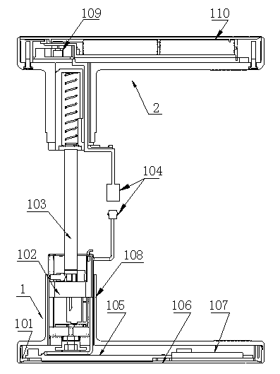
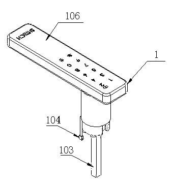
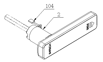
[0021] Embodiment 1: with reference to attached Figure 1-9 and Figure 12 . An intelligent electronic door handle lock, comprising a front handle 1 and a rear handle 2, the front or top surface of the front handle 1 in the front handle 1 is provided with a touch panel 106, and the intelligent controller is located in the handle of the front handle 1, The intelligent controller includes a main control circuit board 105 and a low frequency module 107, a circuit board support 101 is built in the front handle cavity, a touch panel 106 is fixed on one side of the circuit board support 101, and the other side of the circuit board support 101 has a built-in circuit board 105 and a low frequency module 107 , the circuit board 105 data line passes through the front handle shaft to connect the data line plug 104, the electric clutch 102 is built in the front handle shaft cavity 112 and the signal input end of the electric clutch 102 is connected with the signal output end of the circu...

Embodiment 2

[0026] Embodiment 2: On the basis of Embodiment 1, the electric clutch 102 is an electromagnetic clutch, and the manufacturing technology of the electromagnetic clutch is the prior art, so it will not be described here.

Embodiment 3

[0027] Embodiment 3: with reference to attached Figure 7 , Figure 10-12 . An intelligent electronic spherical doorknob lock, which includes a spherical front handle 301 and a spherical rear handle 302. The intelligent controller is located in the handle of the spherical front handle 301. The intelligent controller includes a main control circuit board 105 and a low-frequency module 107. Touch The panel 106 is located on the end face of the spherical front handle 301, the circuit board 105 and the low frequency module 107 are built in the cavity of the spherical front handle 301, the data line of the circuit board 105 passes through the spherical front handle shaft and connects to the data cable plug 104, and the electric clutch 102 is built in the spherical In the front handle shaft cavity 112 and the signal input end of the electric clutch 102 is connected with the signal output end of the circuit board 105, and the end of the electric clutch 102 is plugged with the door l...


PUM


Abstract

The invention relates to an intelligent electronic lock and a control method, wherein an electric clutch is arranged inside an inner hole of a door handle and the electric clutch can be used for directly opening and closing a door lock square key rod. The intelligent electronic lock and the control method comprise an intelligent electronic handling door handle lock or an intelligent electronic spherical door handle lock. The door lock square key rod is matched with a square key sleeve in an inserting mode. The square key sleeve is matched with a front handle shaft hole in a sliding mode. A password controller can be used by a user to control a motor shaft to rotate positively and negatively. An eccentric wheel can be driven by the motor shaft to rotate positively and negatively. The positive rotation and the negative rotation of the eccentric wheel force a movable pin to open and lock the square key sleeve. Furthermore, the square key sleeve can be achieved to brake and lock the door lock square key rod or open the door lock square key rod to achieve a purpose that the door lock square key rod can be used for driving a door lock spring bolt to open or lock . The intelligent electronic lock and the control method has the advantages that the purpose that the electric clutch is integrated with the front handle shaft of the door handle can be achieved; the purpose that a fixing shell of the motor and a shaft shell of the front handle are matched to locate can be achieved; the purposes that the electric clutch is used for directly braking the door lock square key rod and the door lock can be braked without a lock cylinder can be achieved.

Description

technical field [0001] The invention relates to an intelligent electronic lock in which an electric clutch is built in the inner hole of a door handle and adopts the electric clutch to directly open or lock a square key rod of a door lock and a control method thereof, belonging to the field of door handle manufacturing. Background technique [0002] CN1813114A, designation "electromechanical cylinder lock", which interacts with analysis electronics for identifying access authorizations and has a housing comprising two opposing cylinder receptacles in which each is rotatably placed A lock cylinder actuatable by a key or a door knob shaft in each case connected in a rotationally fixed manner to the door knob, wherein the lock cylinder or the door handle shaft cooperates with, in particular, a bolt for actuating the door lock or a lock nose of the latch, Moreover, in the case of the cooperation of the key or the completion of the access authorization authentication, the locking...

Claims


Application Information

Patent Timeline
IPC IPC(8): E05B47/00E05B49/00E05B15/00E05B3/00
Inventor 华林阮宏鸣
Owner HANGZHOU SHTECH
Why Eureka
Try Eureka