Air power drive device

A driving device and aerodynamic technology, applied in the direction of machines/engines, non-variable engines, mechanical equipment, etc., can solve the problems of unusable motors, high energy consumption, environmental pollution, etc., and achieve energy sanitation, energy saving, environmental protection, and portable transportation Convenience and wide application prospects

Inactive Publication Date: 2013-05-15
岳国胜
View PDF8 Cites 4 Cited by
  • Summary
  • Abstract
  • Description
  • Claims
  • Application Information

AI Technical Summary

Problems solved by technology

[0002] Most of the existing power output devices are internal combustion engines or electric motors. Generally, internal combustion engines and electric motors are large in size and inconvenient to carry. If the volume of electric motors or internal combustion engines is made smaller, the output power will be correspondingly reduced, which cannot meet the needs of daily production. Daily needs
The use of electric motors and internal combustion engines will also be restricted by many external conditions. For example, in rural areas, pastoral areas, mountainous areas and islands where the power grid is not popularized, electric motors cannot be used
When using the internal combustion engine, it is necessary to carry corresponding fuel oil, which increases the amount of carrying items. The internal combustion engine consumes a lot of energy when it is used, and it pollutes the environment.

Method used


Image

  • Air power drive device
  • Air power drive device

Examples


Embodiment Construction

[0016] The present invention will be described in detail below in conjunction with the accompanying drawings and embodiments.

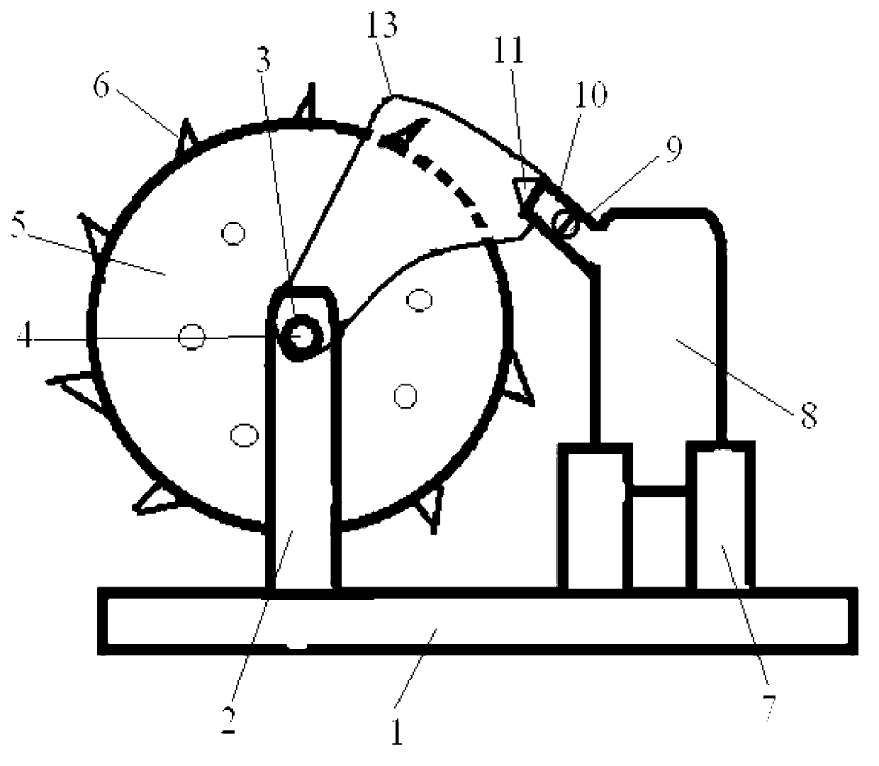
[0017] Such as figure 1 As shown, the present invention utilizes the principle of leverage to inject air into the wheel rim of a runner, push the runner to rotate with the rotating shaft through air force, and use the rotating shaft as the output shaft to output power outward.

[0018] The present invention comprises a base 1, one side of the base 1 is provided with a pair of upright columns 2 as a supporting frame, two bearings 3 are arranged symmetrically on the top of the two upright columns 2, and the two bearings 3 jointly support a rotating shaft 4, and the rotating shaft 4 is fixedly connected with a set Runner 5 between two uprights 2. One end of the rotating shaft 2 protrudes to connect the input shaft of the generator. A plurality of protruding blades 6 as force-bearing elements are provided at intervals on the circumferential edge of the ...


PUM


Abstract

The invention relates to an air power drive device which is characterized by comprising a base. The base is connected with a rotating shaft through a supporting frame. One end of the rotating shaft extends out of the supporting frame and serves as an output shaft. The rotating shaft is fixedly connected with a rotating wheel. A plurality of stress elements are arranged at intervals along the circumferential direction of the rotating wheel. The other side of the base is connected with an air power output device through a support. The air power output device is connected with an air injector pipe through a switch valve. An outlet of the air injector pipe is provided with a high-pressure nozzle. The high-pressure nozzle is aligned to the pushing direction of one stress element on the rotating wheel. As the air power output device and the rotating wheel driven by the air power output device are arranged, air output by the air power output device drives the rotating wheel to drive the rotating shaft to rotate, and the rotating shaft as the power output shaft drives equipment such as a generator connected with the rotating shaft to operate. The air power drive device is ingenious in design, simple in structure, convenient to carry, energy-saving and environment-friendly, and can be widely applied to a power drive process of all kinds of rotating equipment.

Description

technical field [0001] The invention relates to an output device, in particular to an aerodynamic driving device which utilizes compressed air to generate power. Background technique [0002] Most of the existing power output devices are internal combustion engines or electric motors. Generally, internal combustion engines and electric motors are large in size and inconvenient to carry. If the volume of electric motors or internal combustion engines is made smaller, the output power will be correspondingly reduced, which cannot meet the needs of daily production. Daily needs. The use of electric motors and internal combustion engines will also be limited by many external conditions. For example, in areas such as rural areas, pastoral areas, mountainous areas, and islands where the power grid is not popularized, electric motors cannot be used. When using the internal combustion engine, it is necessary to carry corresponding fuel oil, which increases the amount of carrying it...

Claims


Application Information

Patent Timeline
IPC IPC(8): F01D1/02
Inventor 岳国胜
Owner 岳国胜
Why Eureka
Try Eureka