Centrifugal fan

A centrifugal fan and shaft center technology, applied in non-variable pumps, components of pumping devices for elastic fluids, machines/engines, etc., can solve the problem of reduced air intake, affecting heat dissipation performance, and decreased air output, etc. question

Active Publication Date: 2013-05-15
DELTA ELECTRONICS INC
View PDF6 Cites 3 Cited by
  • Summary
  • Abstract
  • Description
  • Claims
  • Application Information

AI Technical Summary

Problems solved by technology

[0004] The surfaces of the upper and lower shells 121, 122 of the existing centrifugal fan are designed as a plane, and there is a gap between the fan blade 112 and the upper and lower shells 121, 122, so when the fluid pressure inside the fan increases to be greater than the external pressure, the fluid will pass through This gap overflows to the air inlets inside the upper and lower shells 121, 122 (as indicated by the arrows), so that the air intake is reduced, and the air output is also reduced, thereby affecting the overall heat dissipation performance.

Method used


Image

  • Centrifugal fan
  • Centrifugal fan
  • Centrifugal fan

Examples


Embodiment Construction

[0043] Hereinafter, a centrifugal fan according to a preferred embodiment of the present invention will be described with reference to related drawings, in which the same components will be described with the same reference signs.

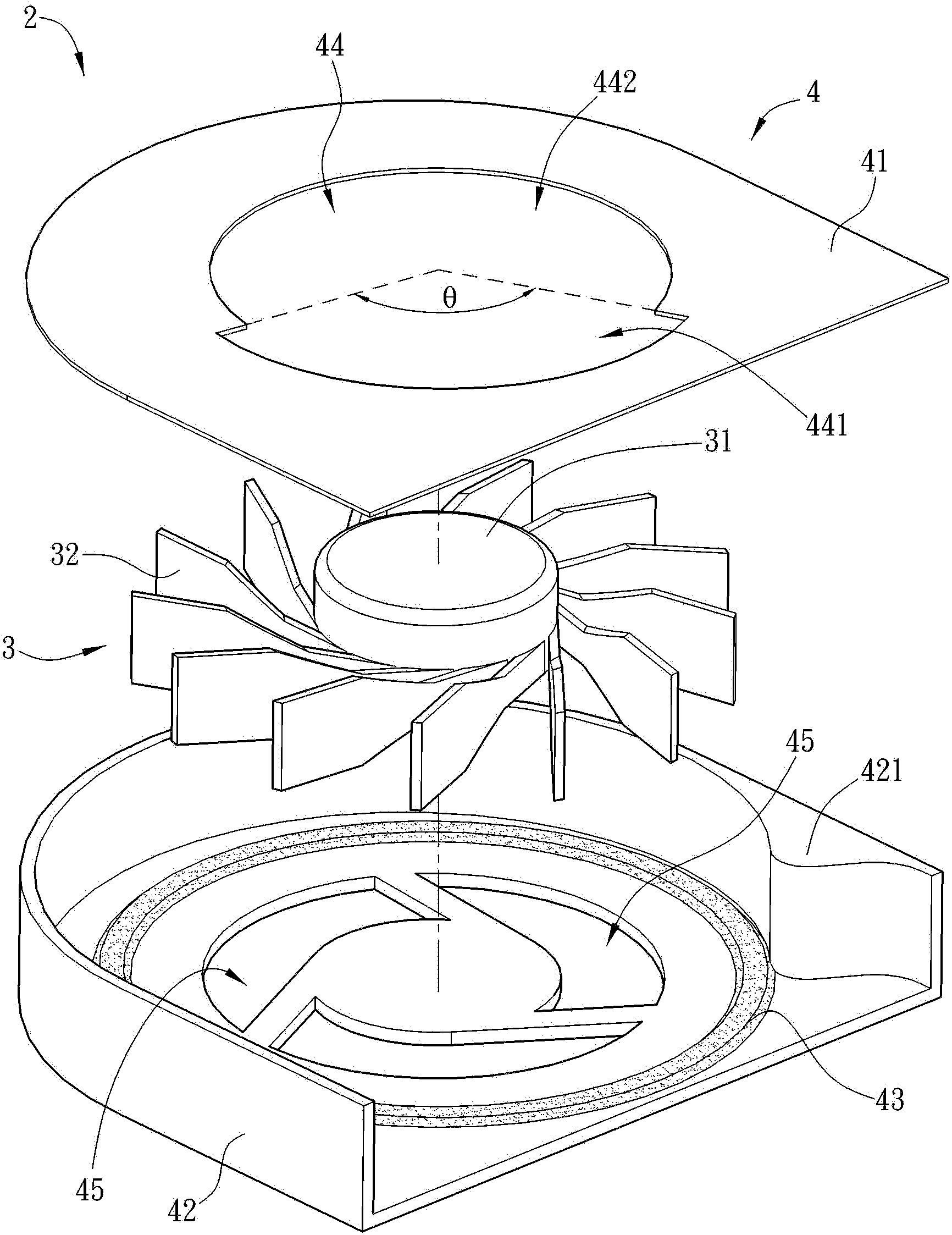
[0044] Please refer to Figure 2A to Figure 2B Shown, where Figure 2A Is an exploded schematic diagram of a centrifugal fan according to a preferred embodiment of the present invention; Figure 2B As basis Figure 2A Schematic diagram of the combined centrifugal fan. The centrifugal fan 2 includes an impeller 3 and a casing 4.

[0045] The impeller 3 has an axis 31 and a fan 32. The fan blade 32 is ringed around the shaft center 31. The impeller 3 is connected to the housing 4 with a shaft center 31.

[0046] The casing 4 covers the impeller 3. The casing 4 has an upper casing 41, a lower casing 42, at least one protrusion 43 and a first air inlet 44. The upper shell 41 and the lower shell 42 are disposed oppositely and connected to each other. In thi...


PUM


Abstract

A centrifugal fan comprises an impeller and a shell body. The impeller comprises a shaft core and a fan blade, and the impeller is covered by the shell body. The shell body comprises an upper shell body, a lower shell body, at least one convex portion and a first air inlet, wherein the convex portion is arranged above at least one of the upper shell body and the lower shell body and positioned around the fan blade, the first air inlet is arranged on the upper shell body, the first air inlet comprises a first area and a second area, and the diameter of the first area is larger than that of the second area. The centrifugal fan can reduce pressure leakage caused by air backflow, can increase air inlet amount by adjusting the size of the air inlet and can achieve the best heat radiation effects.

Description

Technical field [0001] The invention relates to a fan, in particular to a centrifugal fan. Background technique [0002] With the rapid development of the electronics industry, more and more heat is generated by heating electronic components such as chips in electronic products. In order to effectively dissipate the excess heat, a radiator is usually attached to the surface of the heating electronic component, and then a centrifugal fan is installed on the radiator, and the cooling airflow generated by the centrifugal fan is used to forcibly dissipate the radiator, thereby reducing the heat The heat generated by the electronic components is dissipated. [0003] Please refer to Figure 1A and Figure 1B Shown, where Figure 1A Is a top view of a centrifugal fan in the prior art, Figure 1B for Figure 1A Sectional view of the centrifugal fan. The centrifugal fan 1 includes an impeller 11 and a casing 12. The impeller 11 is disposed in the casing 12, the impeller 11 is connected to t...

Claims


Application Information

Patent Timeline
Patent Type & Authority Applications(China)
IPC IPC(8): F04D29/42
Inventor 林星晨黄祥荣
Owner DELTA ELECTRONICS INC
Why Eureka
Try Eureka