Refrigeration cycle apparatus and hot water producing apparatus

A technology of circulation device and decompression device, used in refrigeration and liquefaction, lighting and heating equipment, refrigerators, etc., can solve the problems of complicated refrigeration cycle and increased cost of parts, shortening defrosting time, improving operation efficiency, The effect of high operating efficiency

Inactive Publication Date: 2013-05-15
PANASONIC CORP
View PDF8 Cites 3 Cited by
  • Summary
  • Abstract
  • Description
  • Claims
  • Application Information

AI Technical Summary

Problems solved by technology

However, since the bypass circuit and the second on-off valve are provided, there is a problem that

Method used


Image

  • Refrigeration cycle apparatus and hot water producing apparatus
  • Refrigeration cycle apparatus and hot water producing apparatus
  • Refrigeration cycle apparatus and hot water producing apparatus

Examples


Embodiment approach 1

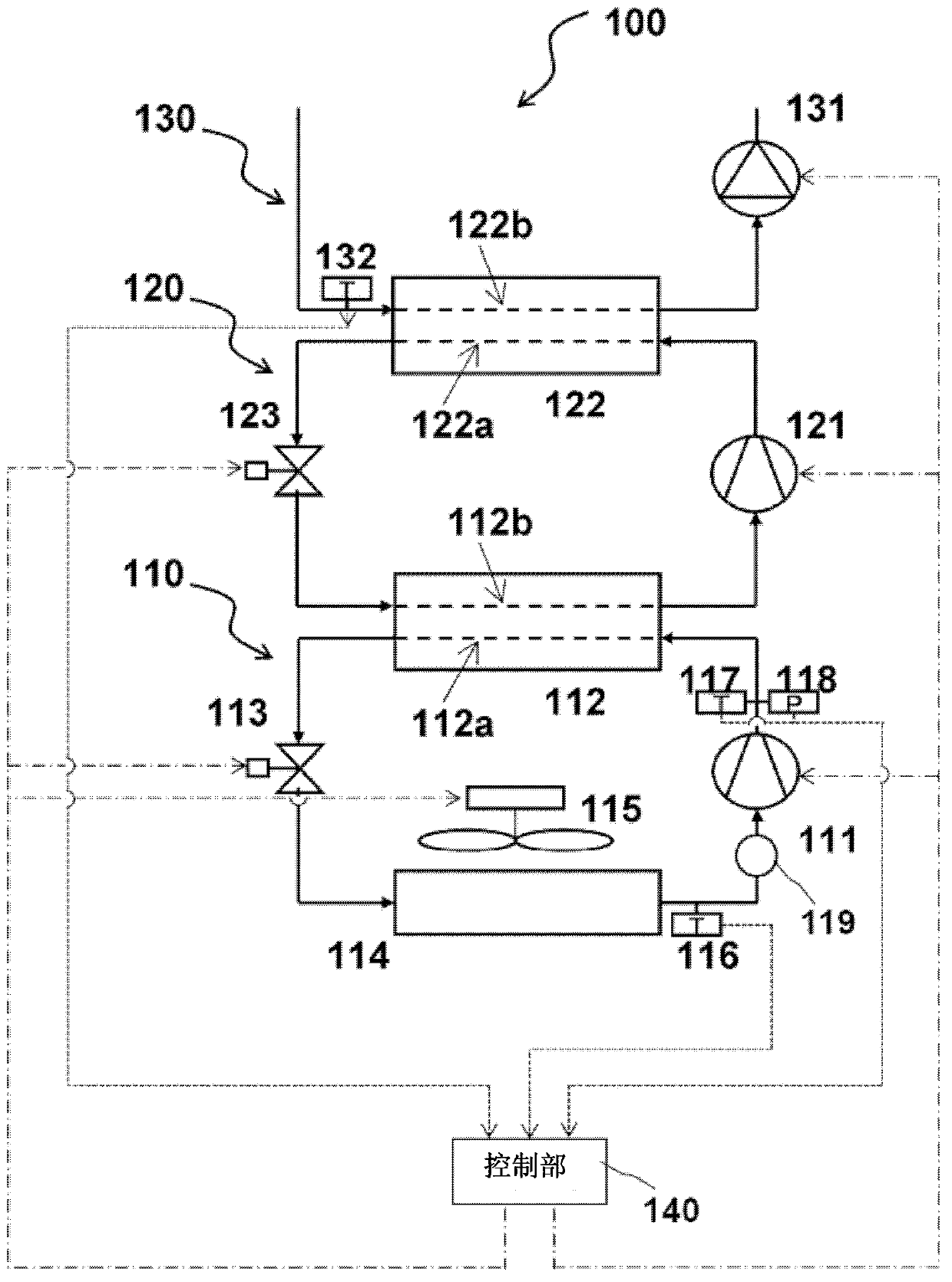
[0078] figure 1 It is a configuration diagram of a binary refrigeration cycle apparatus according to Embodiment 1 of the present invention. The binary refrigeration cycle device 100 is composed of a low temperature side refrigeration cycle 110 , a high temperature side refrigeration cycle 120 , a heat medium cycle 130 , and a control unit 140 .

[0079] The low-temperature side refrigeration cycle 110 is a cascade heat exchange in which the low-temperature side compressor 111 that sucks in the low-temperature side refrigerant in a gaseous state and compresses it, and discharges high-temperature and high-pressure low-temperature side refrigerant, and the low-temperature side refrigerant and the high-temperature side refrigerant perform heat exchange. The device 112, the low-temperature side decompression device 113 for adjusting the flow rate of the low-temperature side refrigerant, and the air heat exchanger (low-temperature side evaporator) 114 for taking heat from the outdo...

Embodiment approach 2

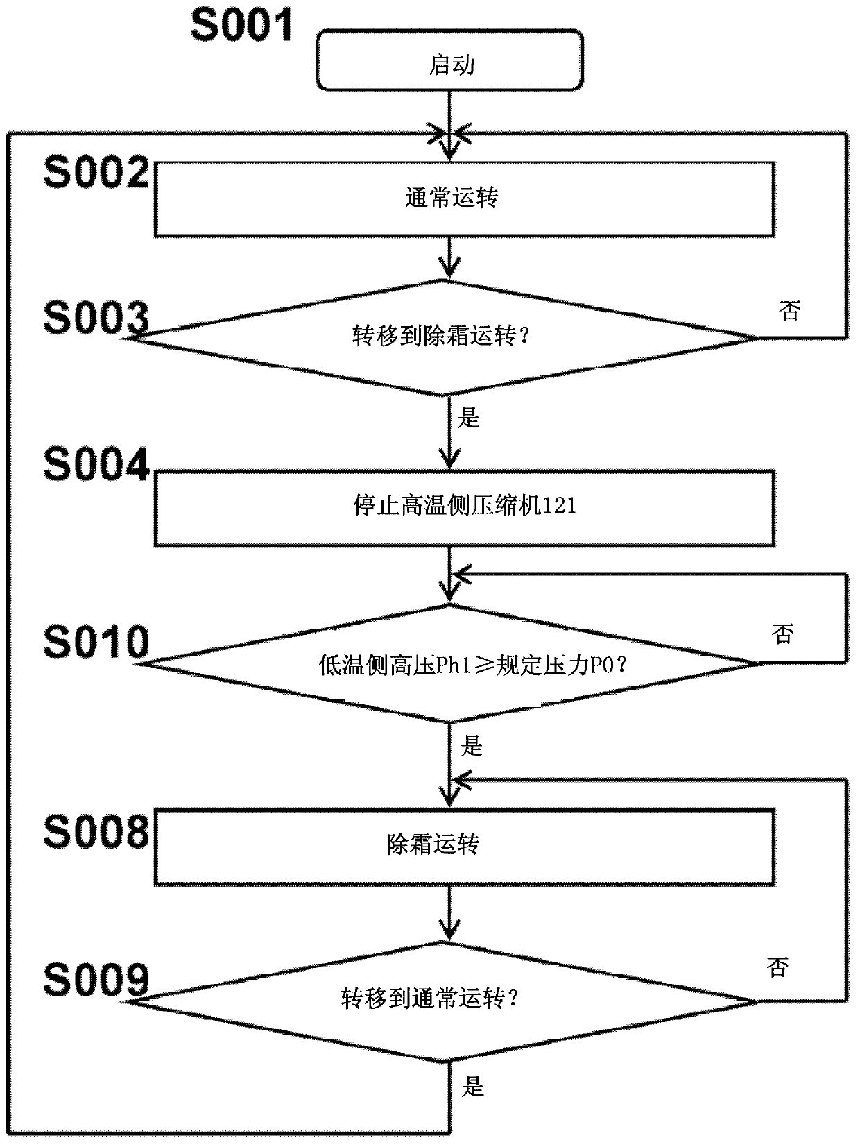
[0113] image 3 It is a flowchart explaining the control operation of the control unit in the second embodiment of the present invention.

[0114] In addition, in this embodiment, the configuration of the binary refrigeration cycle apparatus 100 is the same as figure 1 Since they are the same, descriptions of these constituent elements are omitted.

[0115] image 3 compared to figure 2 , because there are no steps 005 to 007, the process of step 010 is added instead. Other processing and figure 2 The same, so in this embodiment, the operation of step 010 will be mainly described.

[0116] When it is determined in step 003 that the control unit 140 has shifted to the defrosting operation, it stops the high temperature side compressor 121 in the next step 004 . Then, as in the first embodiment, the temperature of the low-temperature side refrigerant flowing through the flow passage 112a in the cascade heat exchanger 112 rises rapidly, and heat is stored from the low-te...

Embodiment approach 3

[0124] Figure 4 It is a flowchart illustrating the control operation of the control unit according to the third embodiment of the present invention.

[0125] In addition, in this embodiment, the configuration of the binary refrigeration cycle apparatus 100 is the same as figure 1 Since they are the same, descriptions of their constituent elements are omitted.

[0126] Figure 4 compared to image 3 (Second embodiment), instead of step 101, the flow of step 011 is added. Other processing and image 3 The same, so in this embodiment, the operation of step 011 will be mainly described.

[0127] When it is determined in step 003 that the control unit 140 has shifted to the defrosting operation, it stops the high temperature side compressor 121 in the next step 004 . Then, as in the first embodiment, the temperature of the low-temperature side refrigerant flowing through the flow passage 112a in the cascade heat exchanger 112 rises rapidly, and heat is stored from the low-t...


PUM


Abstract

A refrigeration cycle apparatus includes a low temperature-side refrigeration cycle 110, a high temperature-side refrigeration cycle 120, defrosting detecting means 116 which detects a frost-formed state of a low temperature-side evaporator 114 of the low temperature-side refrigeration cycle 110. When an operation should be shifted to a defrosting operation for thawing frost of the low temperature-side evaporator 114, an operation of the low temperature-side compressor 111 of the low temperature-side refrigeration cycle 110 is continued, an operation of the high temperature-side compressor 121 of the high temperature-side refrigeration cycle 120 is stopped, and the operation is shifted to the defrosting operation. When the operation is shifted to the defrosting operation, heat-accumulated high temperature low temperature-side refrigerant is supplied to the low temperature-side evaporator 114 to defrost. Therefore, it is possible to shorten the defrosting time and to enhance the operation efficiency of a refrigeration cycle.

Description

technical field [0001] The invention relates to the defrosting control of a binary refrigeration cycle device. Background technique [0002] Currently, there is a heat pump hot water generator capable of heating a heat medium such as water to 65°C to 80°C using a binary refrigeration cycle composed of a high-temperature side refrigeration cycle and a low-temperature side refrigeration cycle (for example, refer to Patent Document 1). [0003] The high-temperature side refrigerant flowing through the high-temperature side refrigeration cycle is evaporated in the cascade heat exchanger by the heat of condensation of the low-temperature side refrigerant flowing through the low-temperature side refrigeration cycle. In addition, in the refrigerant-heat medium heat exchanger installed in the refrigeration cycle on the high temperature side, the heat of condensation of the high temperature side refrigerant is used to heat the heat medium to a high temperature of 65 to 80°C for heati...

Claims


Application Information

Patent Timeline
IPC IPC(8): F25B47/02F25B49/02F24H4/02
CPCF25B25/005F25B47/02F25B2700/11F25B2600/01F25B2600/2513F25B2347/023F25B2700/21152F25B7/00F25B2700/21175F25B2339/047F25B2600/0251F25B2700/1931F25B47/025F25B2600/13Y02B30/70
Inventor 松井大森胁俊二青山繁男
Owner PANASONIC CORP
Why Eureka
Try Eureka