Apparatus and method for die bonding

A technology of solid crystal and mobile devices, which is applied in the fields of electrical solid-state devices, semiconductor/solid-state device manufacturing, electrical components, etc., can solve the time-consuming, difficult to use high-precision crystal-bonding process, and is not suitable for high-precision crystal-bonding Process and other issues, to avoid time-consuming, reduce the steps of die-bonding heating, and achieve the effect of good accuracy

Inactive Publication Date: 2013-05-15
WALSIN LIHWA
View PDF7 Cites 17 Cited by
  • Summary
  • Abstract
  • Description
  • Claims
  • Application Information

AI Technical Summary

Problems solved by technology

However, due to the omission of the die-bonding sucker, this method is difficult to apply to high-precision die-bonding processes
[0006] Therefore, if the known sequential die-bonding method is used in the die-bonding process, it will be obviously time-consuming, and the method of omitting the die-bonding sucker can increase the speed of die-bonding, but it is not suitable for high-precision die-bonding Process

Method used


Image

  • Apparatus and method for die bonding
  • Apparatus and method for die bonding
  • Apparatus and method for die bonding

Examples


Embodiment Construction

[0054] The following examples illustrate the crystal bonding device and the crystal bonding method of the present invention. It should be noted here that the drawings are drawn in a slightly simplified or slightly exaggerated manner, which is to facilitate the understanding of the present invention. this invention.

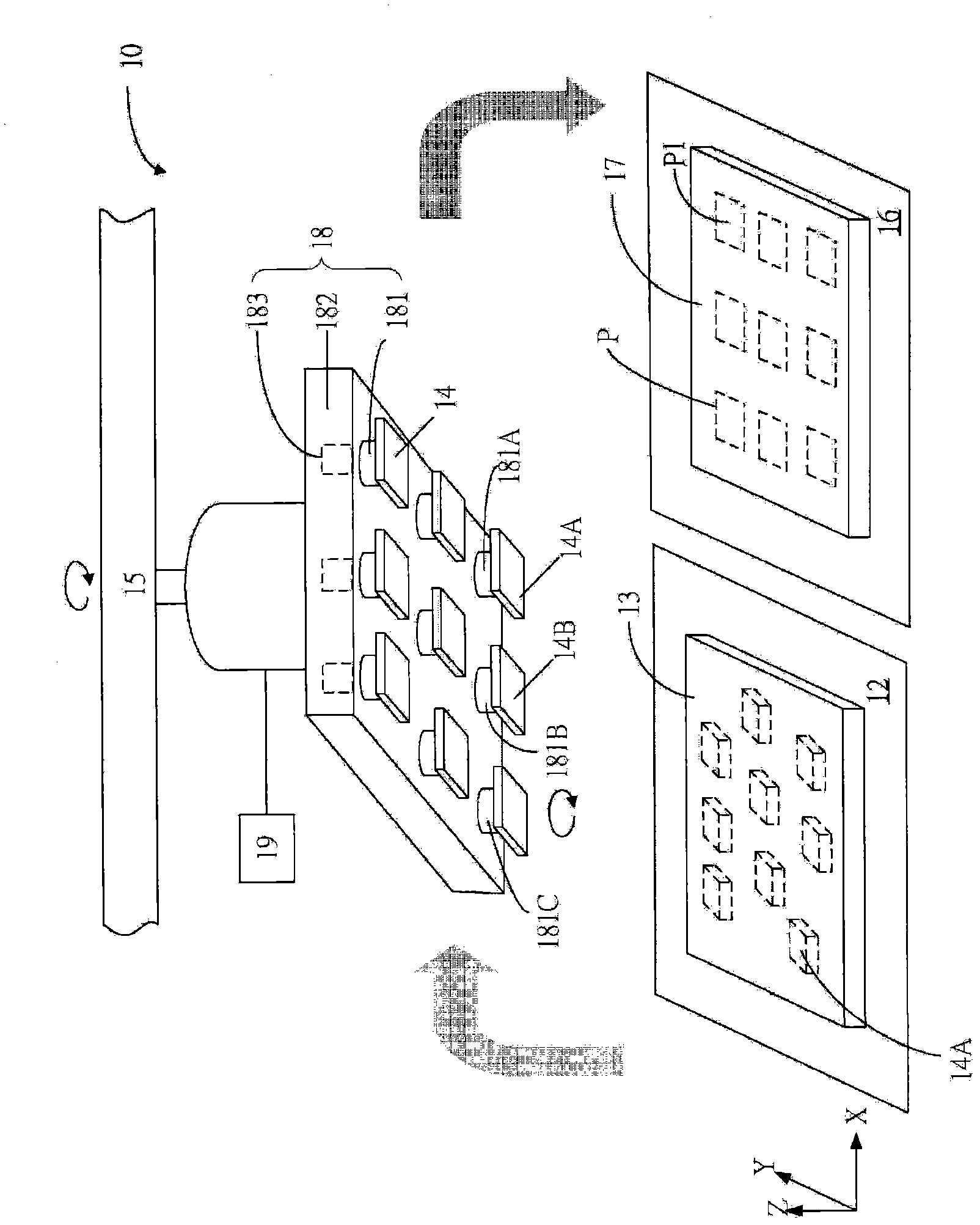
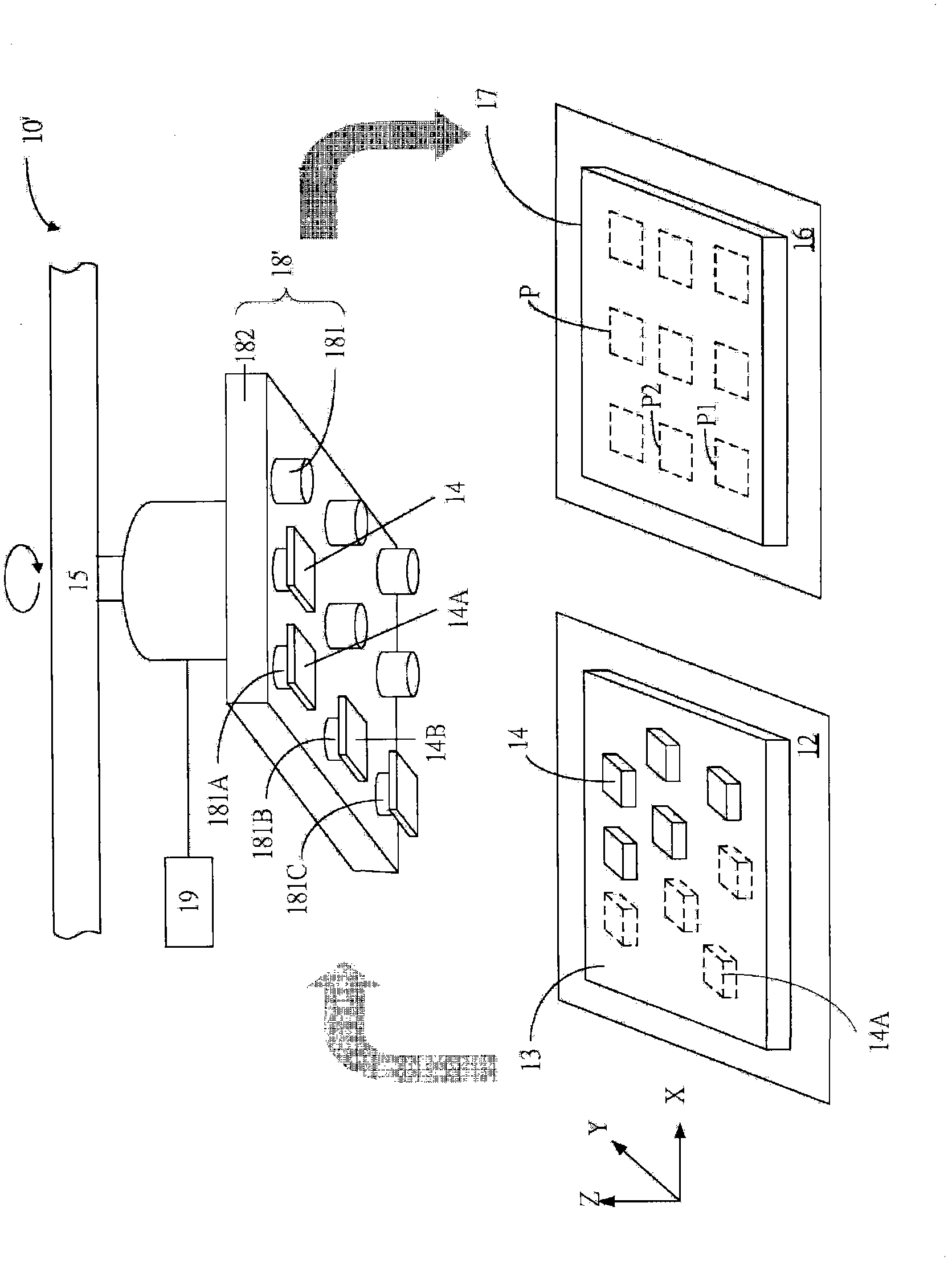
[0055] First, see Figure 1A , which is a schematic diagram of the crystal bonding device 10 according to the first preferred embodiment of the present invention. The die-bonding device 10 of this embodiment is characterized in that it can simultaneously, sequentially, or partly simultaneously / partially pick up multiple dies at one time, and fine-tune the relative positions between the dies to accurately position each die, and then These dies are fixed on the substrate at one time.

[0056] In detail, the die bonding device 10 includes a die aspirator 18 , and the die aspirator 18 has a plurality of suction nozzles 181 . The grain sucker 18 is movably positione...


PUM


Abstract

A die bonding apparatus and a die bonding method are provided, which are capable of simultaneously bonding a plurality of dies from a first placement area onto a substrate disposed on a second placement area. The die bonding apparatus includes a die sucking device which is movably located above the first placement area and a second placement area. The die sucking device includes a plurality of nozzles. The nozzles can suck the dies disposed on the first placement area, and then simultaneously bond the dies onto the substrate.

Description

technical field [0001] The invention relates to a crystal-bonding device and a crystal-bonding method, in particular to a crystal-bonding device and a crystal-bonding method capable of simultaneously bonding multiple crystal grains at one time. Background technique [0002] In recent years, light emitting diodes (Light Emitting Diode, LED) have become the focus of future green light source development due to their energy saving and long service life. At present, when packaging LEDs in the industry, a single sucker with a single suction nozzle is often used to suck the LED dies from the adhesive film one by one and then install them on the substrate (or base) one by one to complete the LED dies. crystal bonding process. Then, follow-up processes such as wire bonding and glue sealing are carried out to further complete the entire package. [0003] The aforementioned traditional die bonding process is a known sequential die bonding method. Since this sequential die bonding me...

Claims


Application Information

Patent Timeline
Patent Type & Authority Applications(China)
IPC IPC(8): H01L33/00H01L21/683
CPCH01L24/97H01L2224/75745H01L33/00H01L21/6838H01L2224/7598H01L2224/75842H01L2224/97H01L21/683H01L24/75H01L2224/75753H01L33/0095H01L2924/12041H01L2924/15787H01L2924/15788Y10T156/1702H01L2924/00
Inventor 锺君炜罗伟诚吴荣崑姜崇义
Owner WALSIN LIHWA
Why Eureka
Try Eureka