Video monitoring cloud platform controlling method and device

A technology of video monitoring and control methods, applied in the direction of using feedback control, TV, color TV, etc., can solve problems such as poor user experience and cumbersome operation

Inactive Publication Date: 2013-05-15
深圳市云宙多媒体技术有限公司
View PDF3 Cites 22 Cited by
  • Summary
  • Abstract
  • Description
  • Claims
  • Application Information

AI Technical Summary

Problems solved by technology

[0004] The purpose of the embodiments of the present invention is to propose a video surveillance pan-tilt control method, aiming at solving the problem that in the prior art in

Method used


Image

  • Video monitoring cloud platform controlling method and device
  • Video monitoring cloud platform controlling method and device
  • Video monitoring cloud platform controlling method and device

Examples


Embodiment 1

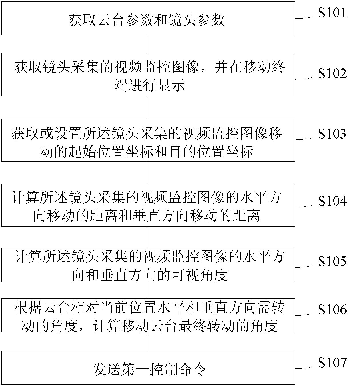
[0044] figure 1 It is a flow chart of a video monitoring pan-tilt control method in a preferred embodiment of the present invention. The embodiment of the invention is a video surveillance pan-tilt control method that only involves camera movement, and the method includes the following steps:

[0045] S101, acquiring pan / tilt parameters and lens parameters;

[0046] The parameters of the pan / tilt include the vertical movement range of the pan / tilt [L1~L2], the horizontal movement of the pan / tilt [L3~L4], and the current position of the pan / tilt. The current position of the pan / tilt includes the current horizontal angle of the pan / tilt, The current vertical angle of the station;

[0047] The lens parameters include the lens CCD width w, the lens CCD height h, the lens CCD focal length range [a~b], and the current focal length f of the lens;

[0048] The pan / tilt parameters and lens parameters can be obtained through an API (Application Programming Interface, Application Progr...

Embodiment 2

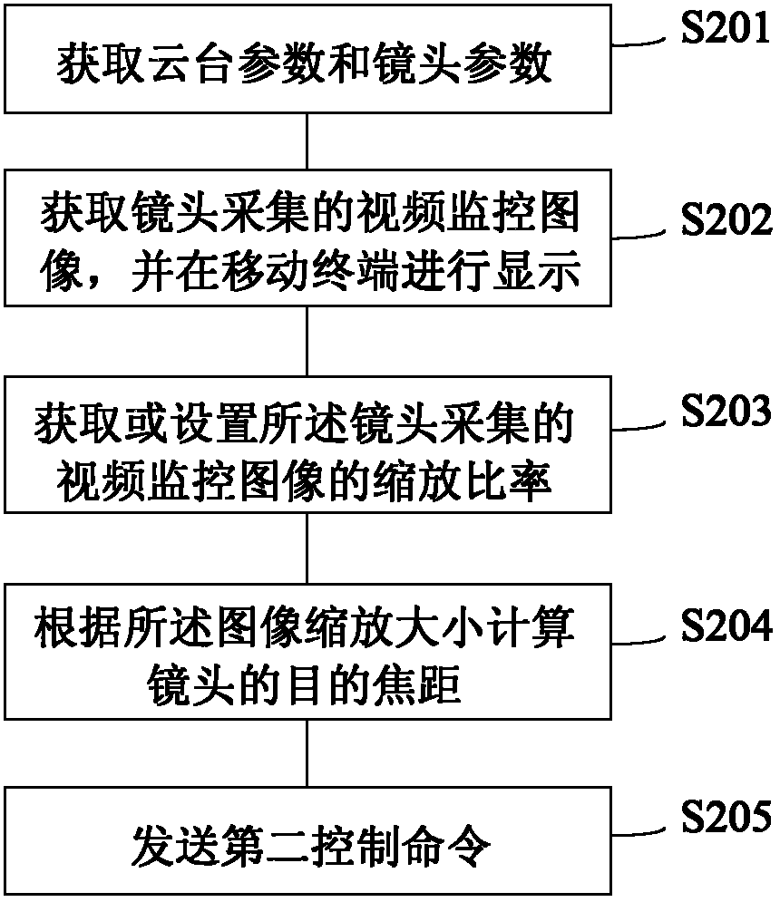
[0073] figure 2 It is a flow chart of a video monitoring pan-tilt control method in a preferred embodiment of the present invention. The embodiment of the invention is a video surveillance pan-tilt control method that only involves lens zooming. The method includes the following steps:

[0074] S201, acquiring pan / tilt parameters and lens parameters;

[0075] The parameters of the pan / tilt include the vertical movement range of the pan / tilt [L1~L2], the horizontal movement of the pan / tilt [L3~L4], and the current position of the pan / tilt. The current position of the pan / tilt includes the current horizontal angle of the pan / tilt, The current vertical angle of the station;

[0076] The lens parameters include the lens CCD width w, the lens CCD height h, the lens CCD focal length range [a~b], and the current focal length f of the lens;

[0077] The pan / tilt parameters and lens parameters can be obtained through an API (Application Programming Interface, Application Programming...

Embodiment 3

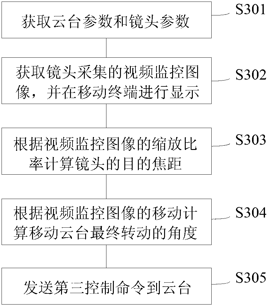
[0090] image 3 It is a flow chart of a video monitoring pan-tilt control method in a preferred embodiment of the present invention. The embodiment of the present invention relates to a video surveillance pan-tilt control method that simultaneously performs lens movement and lens zooming. The method includes the following steps:

[0091] S301, acquiring pan / tilt parameters and lens parameters;

[0092] The parameters of the pan / tilt include the vertical movement range of the pan / tilt [L1~L2], the horizontal movement of the pan / tilt [L3~L4], and the current position of the pan / tilt. The current position of the pan / tilt includes the current horizontal angle of the pan / tilt, The current vertical angle of the station;

[0093] The lens parameters include the lens CCD width w, the lens CCD height h, the lens CCD focal length range [a~b], and the current focal length f of the lens;

[0094] The pan / tilt parameters and lens parameters can be obtained through an API (Application Pro...


PUM


Abstract

The invention discloses a video monitoring cloud platform controlling method and a device and belongs to the field of video monitoring. The video monitoring cloud platform controlling method and the device can obtain cloud platform parameters and lens parameters through a mobile terminal and displays video monitoring images collected by a lens in the mobile terminal. Required rotation angles of the mobile platform and target focal length of the lens are calculated on the mobile terminal based on settings of a user and then a control order is sent to control rotation of a cloud platform or contraction of the lens. With the video monitoring cloud platform controlling method and the device, a monitoring client terminal can visually control the cloud platform so that the lens can accurately be moved to a designated position once or contracted to a required size.

Description

technical field [0001] The invention relates to the field of video monitoring, in particular to a video monitoring pan-tilt control method and device. Background technique [0002] In the monitoring system, the pan / tilt is used to control the movement of the lens in all directions up, down, left, and right, as well as the zoom of the lens. Usually, on the client side, control commands are sent through keyboards, joysticks and other devices. [0003] Such a control method, the user experience is not very good. First of all, click the control button once, or shake the joystick once, the distance the camera moves, or the size of the zoom is a fixed value. It often takes multiple keys, or shaking the joystick to move the camera to the appropriate position, or zoom to the desired size, especially on handheld devices, when there is no keyboard, only an area on the screen can be drawn to display these controls Buttons, which occupy the image display area, are also very clumsy; se...

Claims


Application Information

Patent Timeline
IPC IPC(8): H04N7/18H04N5/232G05D3/12
Inventor 董志
Owner 深圳市云宙多媒体技术有限公司
Why Eureka
Try Eureka