Automatic clamping device for milling crankshaft key groove

An automatic clamping and crankshaft key technology, applied in positioning devices, clamping, milling machine equipment, etc., can solve the problems of long pressing time, poor processing versatility, and high labor intensity of operators.

Inactive Publication Date: 2013-05-22
TIANRUN IND TECH CO LTD
View PDF7 Cites 9 Cited by
  • Summary
  • Abstract
  • Description
  • Claims
  • Application Information

AI Technical Summary

Problems solved by technology

There are two commonly used clamping devices for milling crankshaft keyways: one is that the V-shaped block and the positioning block are directly fixed on the worktable of the milling machine, and are pressed with bolts and pressure plates. The disadvantage of this pressing method is: It takes a long time, the labor intensity of the operator is high, the pressing force is not easy to control, and the positioning of the crankshaft connecting rod neck on the positioning column is unreliable
Another structure is to fix the V-shaped block and the positioning block on the clamp body, and press it with bolts and pressure plates, or use an air cylinder or hydraulic cylinder to automatically compress it. This pressing method also has shortcomings: the V-shaped block and the positioning block The position of the block fixed on the clamp body is relatively fixed, and it can only be adapted to a crankshaft of one length, and the processing versatility is poor. At the same time, there is also the problem that the positioning of the crankshaft connecting rod neck on the positioning column is not reliable.
In addition, because the medium and large crankshafts are heavy, when the crankshaft is directly placed on the rigid V-shaped block, the above two structures are easy to damage the journal.

Method used


Image

  • Automatic clamping device for milling crankshaft key groove
  • Automatic clamping device for milling crankshaft key groove
  • Automatic clamping device for milling crankshaft key groove

Examples


Embodiment Construction

[0020] The present invention will be described and illustrated in detail below in conjunction with the accompanying drawings.

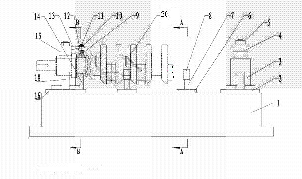
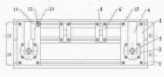
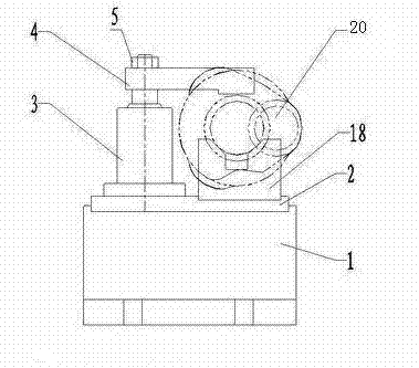
[0021] From figure 1 , figure 2 It can be seen from the figure that an automatic clamping device for milling crankshaft keyways is provided with a base 1 on which a right compression base plate 2, a left compression base plate 16 and two pre-support base plates 6 in the middle are installed.

[0022] The base 1 of the present invention is provided with a groove, and the right compression base plate 2 and the left compression base plate 16 are rectangular plate-shaped structures, and the lengths of the right compression base plate 2 and the left compression base plate 16 are the same as the concave grooves on the base 1. The width of the groove is the same, and the right pressing base plate 2 and the left pressing base plate 16 are installed in the groove. Three longitudinal T-shaped grooves are arranged in the groove of the base. The right compres...


PUM


Abstract

The invention relates to an automatic clamping device for milling a crankshaft key groove. A base of the automatic clamping device for milling the crankshaft key groove is provided with a right pressing base plate, a left pressing base plate and pre-support base plate. The right pressing base plate and the left pressing base plate are respectively provided with a turn angle air cylinder and a support V-shaped block, and the upper end of each turn angle air cylinder is correspondingly connected with a right pressing arm and a left pressing arm. The left pressing base plate is further provided with a connecting rod neck limit block, and a connecting rod neck pressing block support arm is fixed on the left pressing arm. A connecting rod neck pressing block is installed on the connecting rod neck pressing block support arm. A pre-support air cylinder is installed on the pre-support base plate, and is provided with a pre-support V-shaped block. The automatic clamping device for milling the crankshaft key groove is simple in structure and convenient to use, supporting and locating can be adjusted according to the length of a crankshaft to be processed, locating and pressing are reliable, and the damage of a crankshaft journal can be effectively avoided, and the automatic clamping device for milling the crankshaft key groove is ideal.

Description

technical field [0001] The invention relates to a milling machine fixture in the mechanical field, in particular to an automatic clamping device for milling crankshaft key grooves. Background technique [0002] When machining the crankshaft keyway on the milling machine, usually the main journal of the crankshaft is supported on the V-shaped block, and the crankshaft is rotated so that the connecting pin journal of the crankshaft leans against the positioning column, and then the crankshaft is pressed. There are two commonly used clamping devices for milling crankshaft keyways: one is that the V-shaped block and the positioning block are directly fixed on the worktable of the milling machine, and are pressed with bolts and pressure plates. The disadvantage of this pressing method is: It takes a long time, the labor intensity of the operator is high, the size of the pressing force is not easy to control, and the positioning of the crankshaft connecting rod neck on the positi...

Claims


Application Information

Patent Timeline
Patent Type & Authority Applications(China)
IPC IPC(8): B23Q3/00B23C3/30
Inventor 毕可国于冬青
Owner TIANRUN IND TECH CO LTD
Why Eureka
Try Eureka