
Free control cam divider

A cam divider, a technology for controlling cams, which is used in manufacturing tools, metal processing mechanical parts, precision positioning equipment, etc., can solve the problems of reduced efficiency and longer rotation time, and achieves the effect of convenient control

Inactive Publication Date: 2013-05-22
SUZHOU OUBORI AUTOMATION TECH
View PDF6 Cites 47 Cited by
  • Summary
  • Abstract
  • Description
  • Claims
  • Application Information

AI Technical Summary

Problems solved by technology

[0002] The stop time of the standard cam splitter on the market can only be adjusted by adjusting the motor speed to drive the cam splitter to adjust, so that the rotation time is also extended and the efficiency is reduced

Method used


Image

  • Free control cam divider

Examples


Embodiment Construction

[0013] The present invention will be described in detail below with reference to the accompanying drawings and in combination with embodiments.

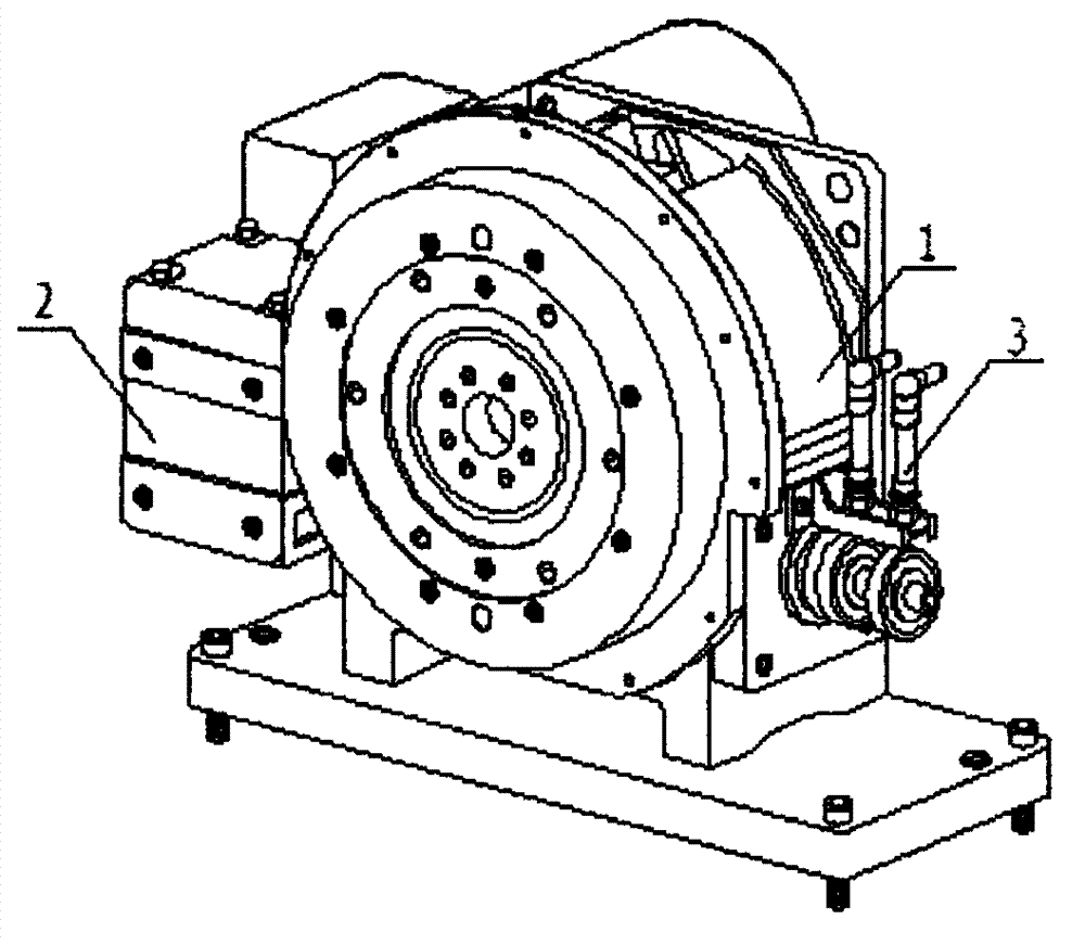
[0014] see figure 1 As shown, a free control cam divider includes a cam divider box 1, one end of the cam divider box 1 is connected to a brake clutch deceleration motor 2, and the other end of the cam divider box 1 is connected to a proximity switch sensor 3.

[0015] Further, the cam splitter case 1 is fixed on the machine platform by screws.

[0016] The above descriptions are only preferred embodiments of the invention, and are not intended to limit the present invention. For those skilled in the art, the present invention may have various modifications and changes. Any modifications, equivalent replacements, improvements, etc. made within the spirit and principles of the present invention shall be included within the protection scope of the present invention.


PUM


Abstract

The invention discloses a free control cam divider which comprises a cam divider box body, one end of the cam divider box body is connected with a belt brake clutch gear motor, the other end of the cam divider box body is connected with an approach switch sensor, and the cam divider box body is fixed on a machine table through screws. Due to the additional approach switch sensor and the additional belt brake clutch gear motor, stop time of the cam divider box boxy can be set freely, when detecting that the divider rotates in place, an approach switch outputs a signal to enable a clutch to be disengaged and a brake to brake. When the process is finished, a signal is output again to enable the clutch to be engaged and the brake to loosen, and the divider is driven to rotate and more convenient to control.

Description

technical field [0001] The invention relates to a cam divider, in particular to a free control cam divider. Background technique [0002] The stop time of the standard cam splitter on the market can only be adjusted by adjusting the motor speed to drive the cam splitter to adjust, so the rotation time is also extended and the efficiency is reduced. Therefore be badly in need of developing a kind of cam divider that can set stop time freely to satisfy the needs of numerous customers. Contents of the invention [0003] In order to solve the above problems, the object of the present invention is to provide a free control cam divider, which is convenient to freely set the stop time. [0004] In order to achieve the above-mentioned technical purpose and achieve the above-mentioned technical effect, the present invention is realized through the following technical solutions: [0005] A free-control cam splitter includes a cam splitter box, one end of the cam splitter box is co...

Claims


Application Information

Patent Timeline
IPC IPC(8): B23Q16/02
Inventor 谢敏富
Owner SUZHOU OUBORI AUTOMATION TECH
Learn More