Water closet with deodorizing device

A technology for toilets and toilets, applied in water supply devices, sanitary equipment for toilets, buildings, etc., can solve the problems of complicated installation, unsightly, loud noise, etc., and achieve the effects of convenient installation and use, clean air, and reasonable design

Active Publication Date: 2014-12-10
夏立君
View PDF9 Cites 3 Cited by
  • Summary
  • Abstract
  • Description
  • Claims
  • Application Information

AI Technical Summary

Problems solved by technology

[0002] Flush toilets have improved the environment for people to go to the toilet, but there is always a peculiar smell during the process of going to the toilet, and the diffused smell is difficult to discharge, causing air and environmental pollution and affecting physical and mental health
This problem is usually solved by installing a toilet deodorizing device. There are two types of existing toilet deodorizing devices: 1. The toilet seat ring and the rotating shaft are designed as a hollow suction channel, and the exhaust is connected through a pipeline. The inlet and exhaust ports of the machine are discharged into the sewer or outdoors. The disadvantage is that this type of device does not match with various toilets, the installation is complicated, and it is not beautiful
2. Use the flushing channel to inhale and exhaust to deodorize. When people leave the toilet, the negative pressure is unable to control the odor overflow. If the inhalation volume is large, water will be sucked back into the exhaust machine when flushing, and the noise is also very loud
In these two ways, the exhaust pipe must pass through the bottom of the water tank and directly lead to the sewer or be discharged outdoors, which makes the overall effect of the toilet poor and unsightly, and increases the difficulty of toilet installation.

Method used


Image

  • Water closet with deodorizing device
  • Water closet with deodorizing device
  • Water closet with deodorizing device

Examples


Embodiment Construction

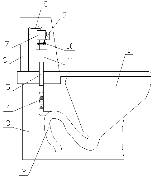
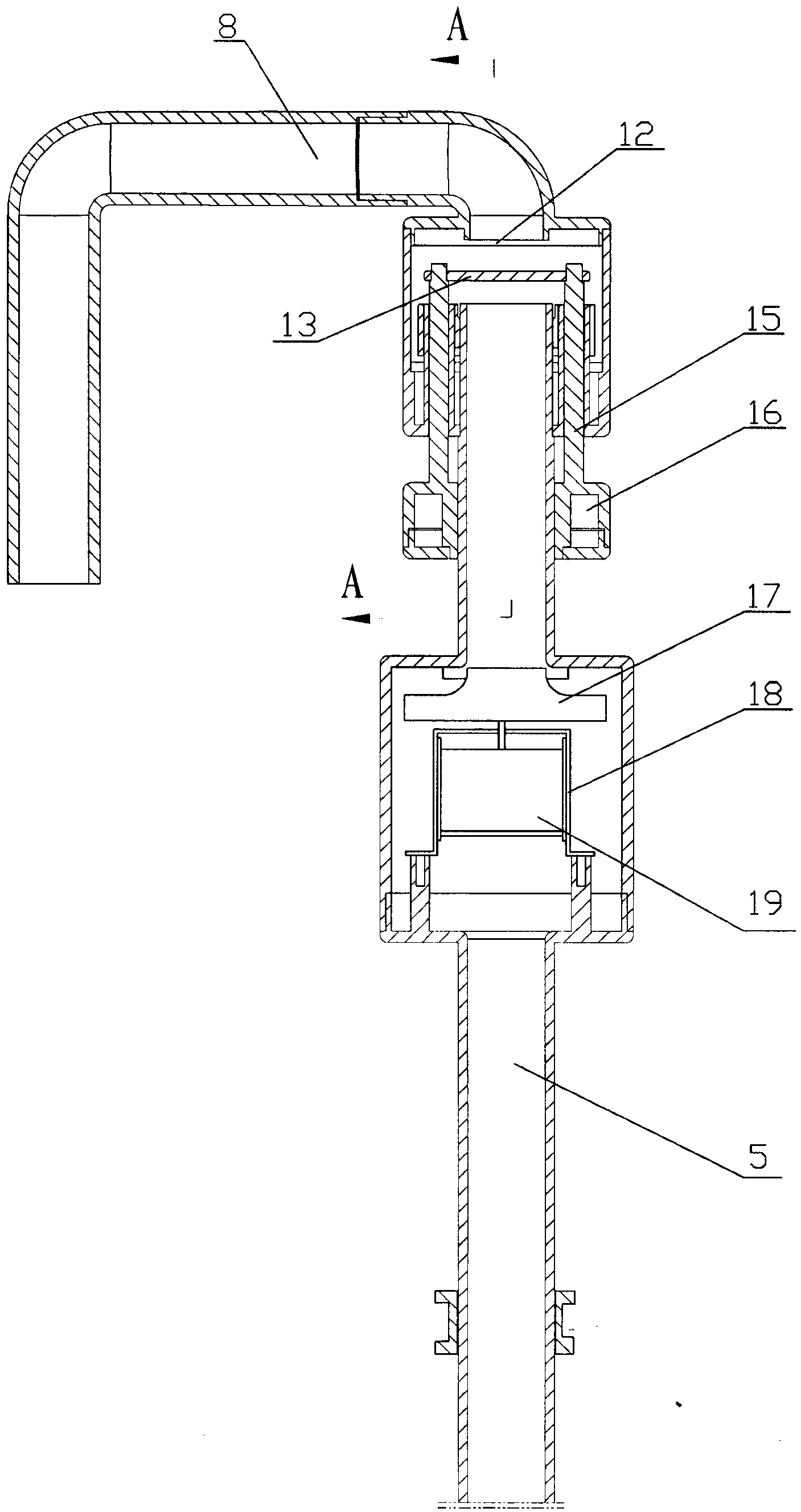
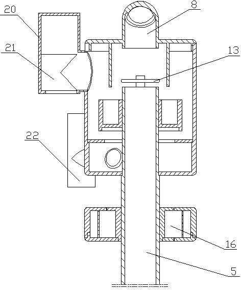
[0020] Reference attached figure 1 , a toilet with a deodorizing device, comprising a toilet body 1 and a water tank 6, a suction and exhaust device is installed in the toilet water tank 6, and the suction and exhaust device includes an air intake pipe 8 and an exhaust pipe 5, The intake pipe 8 is connected with the overflow pipe in the water tank 6, the joint of the intake pipe 8 and the overflow pipe is provided with a sealing ring, the exhaust pipe 5 is provided with an exhaust fan 11, and the air intake pipe 8 and the exhaust pipe 5 There is a multi-functional water and air valve 7 between them, and the exhaust pipe 5 extends downward through the bottom of the water tank 6 to the compartment 3 at the rear of the toilet bowl. The sewage discharge S-bend 2 of the toilet in the compartment 3 communicates, and the joint between the corrugated hose 4 and the toilet sewage S-bend 2 is set at any position between the high point of the sewage S-bend 2 and the outlet.

[0021] Des...


PUM


Abstract

A water closet with a deodorizing device comprises a water closet body and a water tank, an air exhausting device is mounted in the water tank and comprises an air inlet pipe and an air exhaust pipe, the air inlet pipe is connected with an overflow pipe in the water tank, an air exhaust fan is arranged in the air exhaust pipe, a multifunctional water and air valve is arranged between the air inlet pipe and the air exhaust pipe, the air exhaust pipe downwardly penetrates through the bottom of the water tank and extends a separation cavity on the rear portion of a urinal of the water closet body, the lower end of the air exhaust pipe is communicated with a water closet S-shaped bent sewage discharging pipe in the urinal via a corrugated pipe, and the joint of the corrugated pipe and the S-shaped bent sewage discharging pipe is arranged at any position between the top point of the S-shaped bent sewage discharging pipe and a discharging port. The deodorizing device exhausts odor via the water closet S-shaped bent sewage discharging pipe, so that a pipeline does not need to be led out of the water closet body to connect a sewer pipeline. The water closet is simple in design, convenient to mount and use, compact in structure, attractive in appearance, free of external exhausting fans and capable of keeping air in a toilet clean, and has the functions of saving electricity and water.

Description

technical field [0001] The invention relates to a flushing toilet in a toilet, in particular to a toilet with a deodorizing device. Background technique [0002] Flush toilets have improved the environment for people to go to the toilet, but there is always a peculiar smell in the process of going to the toilet, and the diffused peculiar smell is difficult to discharge, causing air and environmental pollution, and affecting physical and mental health. Usually, this problem is solved by installing a toilet deodorizing device. The existing toilet deodorizing device has the following two types: 1. The toilet seat ring and the rotating shaft are designed as a hollow suction channel, and the exhaust is connected through a pipeline. The air intake and exhaust interface of the machine is discharged into the sewer or outdoors. The disadvantage is that this type of device is not matched with various toilets, the installation is complicated, and it is not beautiful. 2. Use the flush...

Claims


Application Information

Patent Timeline
Patent Type & Authority Patents(China)
IPC IPC(8): E03D9/05E03D9/052
Inventor 夏立君
Owner 夏立君
Why Eureka
Try Eureka