
Filter device for use with machine

a filter device and machine technology, applied in the direction of liquid degasification, auxiliary pretreatment, separation processes, etc., can solve the problems of reducing the efficiency of the gas turbine and the inability to replace the filter, so as to improve the efficiency, improve the efficiency, and improve the effect of filter device life and pressure loss

Active Publication Date: 2013-04-09
PARKER INTANGIBLES LLC
View PDF7 Cites 4 Cited by
  • Summary
  • Abstract
  • Description
  • Claims
  • Application Information

AI Technical Summary

Benefits of technology

The patent is about a filter device that improves the efficiency, cost, construction time, filter life, and pressure loss of a filter used with a machine that requires clean airflow. The filter device includes a housing with a permeable filter media that filters the air passing through the housing. This helps to keep the airflow clean and free of particles.

Problems solved by technology

This resistance increases the pressure drop across the airflow inlet system and leads to a decrease in the efficiency of the gas turbine.
Furthermore, replacement of the filters cannot occur until operation of the gas turbine is stopped.

Method used


Image

  • Filter device for use with machine
  • Filter device for use with machine
  • Filter device for use with machine

Examples


Embodiment Construction

[0013]As indicated above, aspects of the invention provide for efficiently filtering particles for a machine requiring a clean airflow. As used herein, the example of a gas turbine will be used to describe aspects of the invention and the prior art. It is understood that a gas turbine is merely one example of a machine requiring clean airflow to which the teachings of the invention may be applied. For example, the teachings of the invention may be similarly applied to other machines such as steam or wind turbines. In any case, use of the term “machine” or “gas turbine” does not limit the teachings of the invention to such specific types of machines requiring clean airflow.

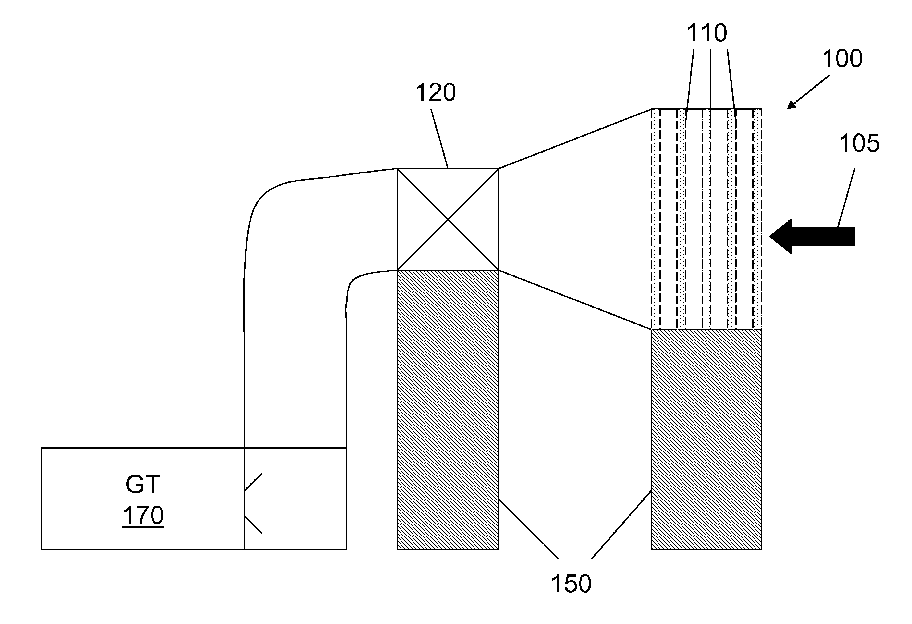
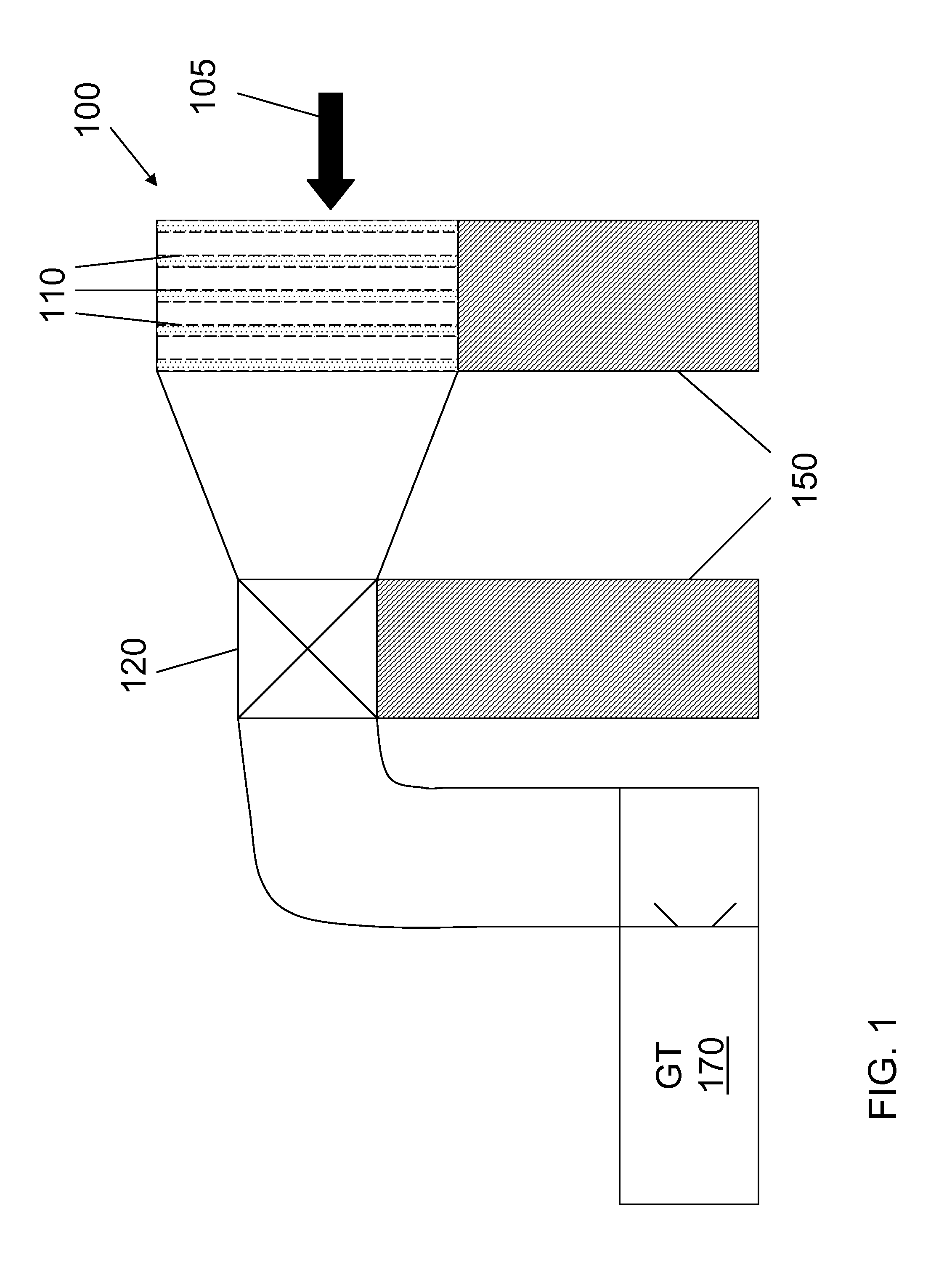
[0014]Turning to the drawings, FIG. 1 shows a side view of a conventional filter device 100 for use with a machine 170 requiring a clean airflow (illustrated as a gas turbine (GT) 170 merely as an example). Filter device 100 is shown including a plurality of filters 110 for removing foreign particles from airflow 1...


PUM

PropertyMeasurementUnit
semi-spherical shapeaaaaaaaaaa
geodesic dome shapeaaaaaaaaaa
flexibleaaaaaaaaaa

Abstract

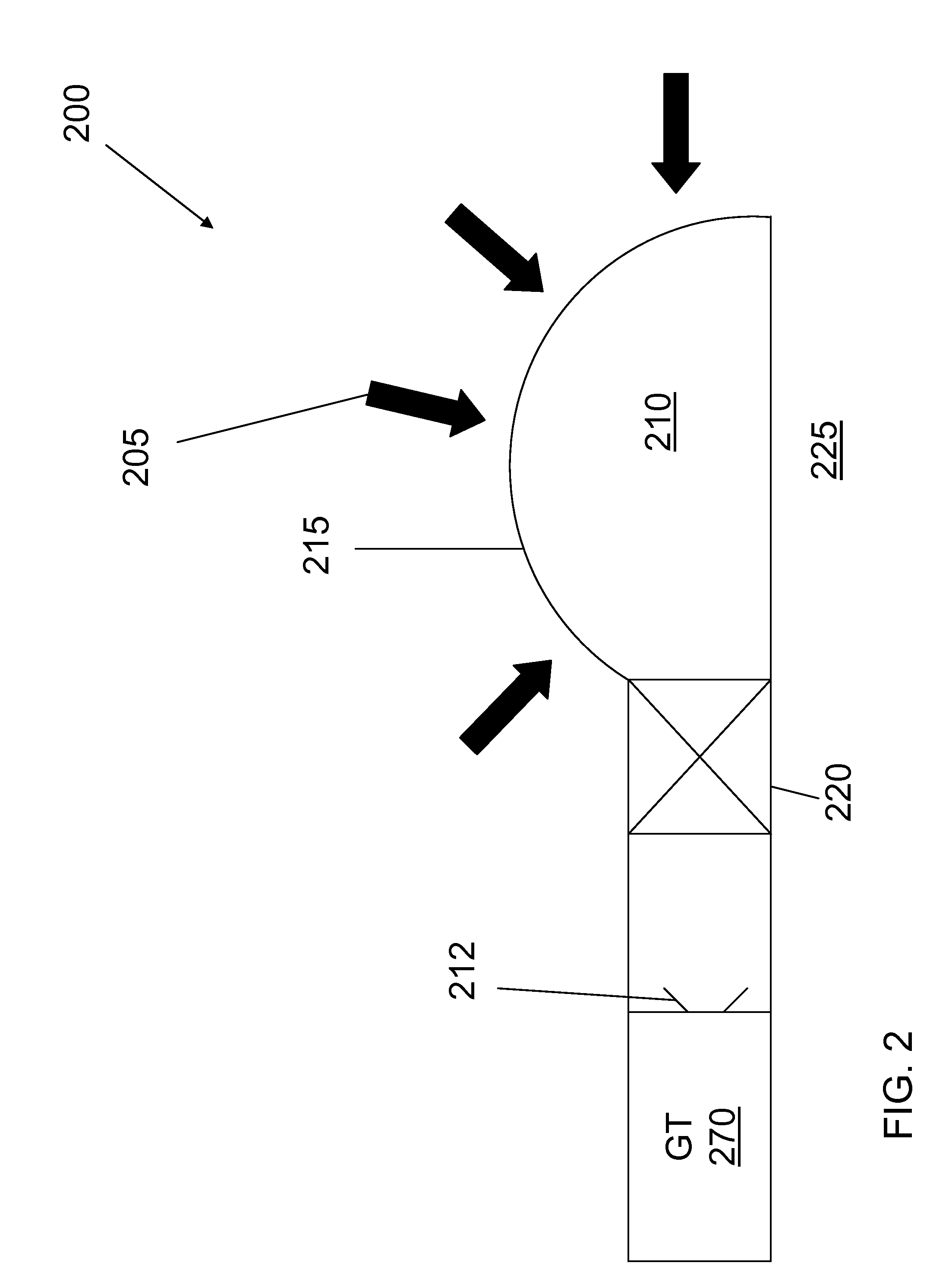
Solutions for improving efficiency of a filter device for use with a machine requiring clean airflow are disclosed. In one embodiment, the filter device includes: a filter housing about an airflow inlet of the machine, wherein the filter housing comprises an air-permeable filter media configured to filter particles from multi-directional airflow moving through a substantial portion of the filter housing into the airflow inlet.

Description

BACKGROUND OF THE INVENTION[0001]The subject matter disclosed herein relates to a filter device for use with a machine. Specifically, the subject matter disclosed herein relates to a filter device for use with a machine requiring clean airflow that filters particles from the air so that the machine can operate efficiently.[0002]There are certain types of machines that require a clean airflow in order to operate properly and efficiently. One example of this type of machine is a gas turbine. During operation of a gas turbine, a compressor draws in air from the surrounding environment and compresses the air into a combustion chamber. In the combustion chamber, the air is mixed with a supplied fuel that is ignited. This creates high temperature combustion gases that drive the gas turbine.[0003]In order to operate efficiently, clean airflow must be provided to the airflow inlet of the gas turbine. A filtration system for a gas turbine usually has a filter device with a plurality of filte...

Claims


Application Information

Patent Timeline
Patent Type & Authority Patents(United States)
IPC IPC(8): B01D49/00
CPCB01D46/0002B01D46/103
Inventor HINER, STEPHEN DAVIDADAMS, MICHAEL T.BRAKE, CHARLES EDWARD THOMAS
Owner PARKER INTANGIBLES LLC
Learn More