A manual rotary hydraulic reversing valve

A hydraulic reversing valve and rotary type technology, applied in the field of hydraulic reversing valve, can solve the problems of system temperature rise, hydraulic system power loss, hidden dangers of personal safety and safety of hydraulic system, etc., achieve large flow, improve energy efficiency, and improve use effect of life

Active Publication Date: 2015-07-29
JIASHAN HANDIJACK TOOLS
View PDF7 Cites 0 Cited by
  • Summary
  • Abstract
  • Description
  • Claims
  • Application Information

AI Technical Summary

Problems solved by technology

[0004] Regarding the positioning structure of the operating handle, the commonly used manual rotary hydraulic reversing valve handle positioning method generally adopts a steel ball positioning structure, and the number of gears is set according to the number of reversing valves. This structure has been proved by practice to have the following operational safety and technical problems. First, the operating handle of the positioning structure, when in use, the handle is pre-stopped on the corresponding valve position of the reversing valve according to the work progress of the actuator, so that the oil circuit of the reversing valve is always open, and when there is no operator or the operator forgets to operate the reversing Under the condition of the valve, the actuator operates continuously, which poses a great safety hazard to the equipment, hydraulic system and even personal safety; second, the hydraulic system operates continuously for a long time, and the excess oil flows back to the oil tank through the overflow valve, causing unnecessary power of the hydraulic system. losses, and increase the system temperature

Method used


Image

  • A manual rotary hydraulic reversing valve
  • A manual rotary hydraulic reversing valve
  • A manual rotary hydraulic reversing valve

Examples


Embodiment Construction

[0027] The present invention will be further described below in conjunction with specific examples.

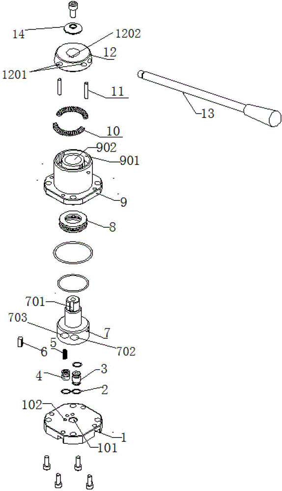
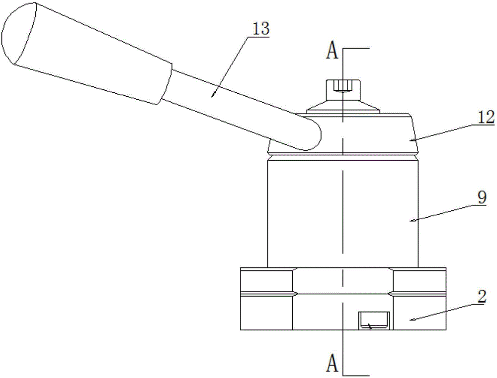
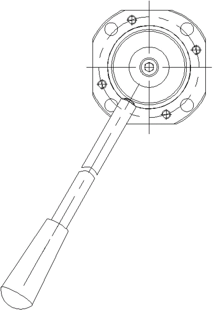
[0028] see Figure 1-Figure 5 , the rotary valve sleeve 9 has a rotary spool mounting hole 902, the rotary spool mounting hole 902 is a stepped two-stage type, which is equipped with a thrust ball bearing 8, the outer diameter of the thrust ball bearing 8 seat ring and the rotary spool mounting hole The inner wall of the 902 hole is tightly fitted, and the rotary valve core 7 is provided with a stepped shaft and tightly fitted with the inner hole of the shaft ring of the thrust ball bearing 8, that is, the thrust ball bearing 8 is interposed between the rotary valve core 7 and the rotary valve sleeve 9 for The axial positioning of the counter-rotating spool 7 supports the rotation of the rotary spool 7 .

[0029] A groove is provided on the inner wall of the rotary valve core mounting hole 902 of the rotary valve sleeve 9 for installing a side O-ring. The side O-ring is inter...


PUM


Abstract

The invention relates to a manual rotary type hydraulic reversing valve which is characterized by comprising a rotary valve sleeve (9), a rotary valve core (7) and a rotary sleeve (12). An annular groove (901) is formed outside a rotary valve core installation hole (902) of the rotary valve sleeve (9). A reset spring (10) is horizontally arranged in the annular groove (901). A fixed pin (11) separates the annular groove (901) and the reset spring (10). The fixed pin (11) is in rigid connection with the rotary sleeve (12) and rotates along with the rotary sleeve (12). The manual rotary type hydraulic reversing valve further comprises a rotary valve oil distribution board (1) which is fixedly connected with a lower end face of the rotary valve sleeve (9), and a center oil way hole (101) and at least two reversing oil way holes (102) are formed in the rotary valve oil distribution board (1). Reversing grooves corresponding to the reversing oil way holes (102) are formed in the lower portion of the rotary valve core (7). A reversing oil communication nozzle (4) is arranged in each reversing groove. Each reversing oil communication nozzle (4) is pressed and fixed on the rotary valve core (7) through a pressure spring (5) and seal between each reversing oil communication nozzle (4) and the rotary valve core (7) is plane seal.

Description

technical field [0001] The invention relates to a hydraulic reversing valve, specifically a manual rotary hydraulic reversing valve, which belongs to the technical field of hydraulic reversing valves. Background technique [0002] The hydraulic system is widely used in various fields of the machinery industry. The reversing valve makes the reciprocating or rotating hydraulic actuator change the direction of motion. The on-off relationship of the oil port realizes the connection of each oil circuit, cuts off or changes the direction of the liquid flow. [0003] At present, the commonly used manual rotary hydraulic reversing valve usually adopts the oil groove structure arranged axially on the valve core, which is sealed by the gap between the outer circle of the valve core and the inner wall of the valve core installation hole on the valve seat. Balance, valve core and valve seat hole are easy to wear, resulting in gap seal failure, large pressure loss, low efficiency, and s...

Claims


Application Information

Patent Timeline
Patent Type & Authority Patents(China)
IPC IPC(8): F15B13/02
Inventor 金月明
Owner JIASHAN HANDIJACK TOOLS
Why Eureka
Try Eureka