
Mobile object encoding and decoding device, and railway bogie positioning device and method

A technology of encoding and decoding and rail car, applied in the field of rail car positioning device and moving object encoding and decoding, can solve the problems of high cost, complex structure, low positioning accuracy of positioning device, etc., and achieve low cost, simple device structure and accurate positioning. Effect

Inactive Publication Date: 2013-05-22
HENAN UNIV OF SCI & TECH
View PDF4 Cites 9 Cited by
  • Summary
  • Abstract
  • Description
  • Claims
  • Application Information

AI Technical Summary

Problems solved by technology

[0007] The purpose of the present invention is to provide a moving object encoding and decoding, track car positioning device and method to solve the problems of low positioning accuracy, complex structure and high cost of existing positioning devices

Method used


Image

  • Mobile object encoding and decoding device, and railway bogie positioning device and method
  • Mobile object encoding and decoding device, and railway bogie positioning device and method
  • Mobile object encoding and decoding device, and railway bogie positioning device and method

Examples


Embodiment 1

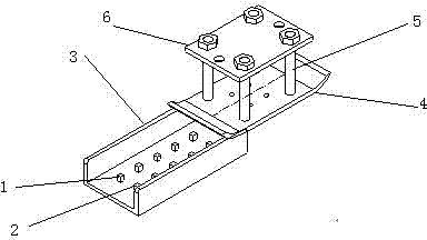
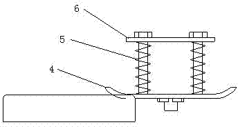
[0040] Such as figure 1 , 1 is a group of code bits, 2 is a group of code reading bits, 3 is a code disc, 4 is a boat-shaped bottom plate of a track trolley, 5 is a floating suspension pin, and 6 is a mounting bracket.

[0041]In this embodiment, the code disk is arranged on the ground between the two tracks where the rail trolley travels, and is located at the position of the work station where the rail trolley needs to stop. The coding bits are arranged side by side on the bottom plate of the coding disc, and the reading bits are set in one-to-one correspondence with the coding bits of the coding disc. On the coding bits, according to the coding method, an encoding induction block is set on the required coding bits. Each reading bit Both are provided with code-reading induction blocks. In this embodiment, both the code-reading induction block and the encoding induction block are metal blocks, wherein the encoding metal blocks are used to encode each operation site of the rai...

Embodiment 2

[0054] In this embodiment, the coding disk is arranged at the position before the parking operation site of the rail trolley, and a positioning disk is also provided on the basis of Embodiment 1, and the positioning disk is also arranged on the ground between the two tracks where the rail trolley travels. , the positioning plate is installed on the accurate parking position of the track trolley, and is used to position the track trolley, such as Figure 6 , 9 is a positioning metal block, which is located on the base plate of the positioning plate, corresponding to the accurate parking position of the track car.

[0055] When the rail trolley travels to the coding disc, after determining the code of the coding disc, if it is the station where it is going to stop, the rail trolley will slow down. When it reaches the positioning disc and detects the pulse signal sent by the positioning metal block , Immediately control the parking operation of the track trolley.

[0056] In oth...


PUM


Abstract

The invention relates to a mobile object encoding and decoding device and railway bogie positioning device and method. The mobile object encoding and decoding device comprises an encoding plate and two travel switches used for transmitting pulse signals, wherein the encoding plate is arranged on an object, and the two travel switches are arranged on the other object moving relative to the former object. A row of encoding positions and a row of code reading positions are parallelly arranged on the encoding plate along the relative moving direction and correspond to each other one by one. Encoding sensing blocks are arranged on the corresponding encoding positions according to the encoding way. Code reading blocks are arranged on the code reading positions correspondingly. The two travel switches, the encoding positions and the code reading positions of the encoding plate are arranged in parallel, wherein one of the travel switches is used for detecting the encoding sensing blocks, and the other travel switch is used for detecting the code reading sensing blocks. The mobile object encoding and decoding device is applied to the field of positioning of railway bogies, so that positioning is more accurate, and the problems about low positioning accuracy, complicated structure and high cost of an existing mobile object positioning device are solved.

Description

technical field [0001] The invention relates to a device and method for coding and decoding a moving object and positioning a rail trolley. Background technique [0002] With the rapid development of science and technology, the manufacturing industry has entered a new stage of development. The continuous and fast production rhythm not only has higher requirements for production equipment, but also has higher requirements for material preparation and feeding speed. The rail trolley is mainly used in the industrial environment of long-distance fixed-track reciprocating transportation operations. It can provide a platform for multiple operations in the transportation section and realize system integration. The track trolley is generally composed of a horizontal track, a chassis, a drive system, a composite operating mechanism, and an electrical control. Only when the trolley stops accurately at the predetermined position required by the operation can each operation link be ef...

Claims


Application Information

Patent Timeline
Patent Type & Authority Applications(China)
IPC IPC(8): G05D1/02G01D5/249
Inventor 王俊张伏毛鹏军徐锐良李树强邱兆美
Owner HENAN UNIV OF SCI & TECH
Learn More