A 3D modeling method for hole edge cracks based on finite element software

A finite element and crack technology, applied in the field of damage tolerance analysis, can solve the problems of poor automation, high difficulty of three-dimensional crack model at the edge of the hole, and long time, and achieve the effect of high automation, strong versatility, and clear method steps

Active Publication Date: 2016-01-06
空军工程大学
View PDF1 Cites 0 Cited by
  • Summary
  • Abstract
  • Description
  • Claims
  • Application Information

AI Technical Summary

Problems solved by technology

[0006] In order to overcome the disadvantages of the prior art, such as high difficulty, long time, and poor degree of automation, in establishing a three-dimensional crack model at the edge of a hole, the present invention provides a method for establishing a three-dimensional penetrating crack at the edge of a hole with a general-purpose finite element software.

Method used


Image

  • A 3D modeling method for hole edge cracks based on finite element software
  • A 3D modeling method for hole edge cracks based on finite element software
  • A 3D modeling method for hole edge cracks based on finite element software

Examples


Embodiment 1

[0038] Example 1: Modeling of three-dimensional penetrating cracks on both sides of through-holes

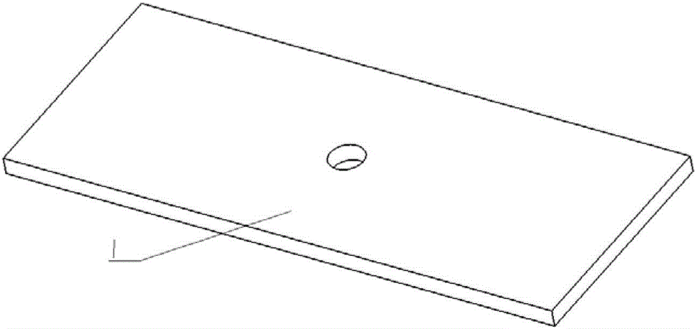
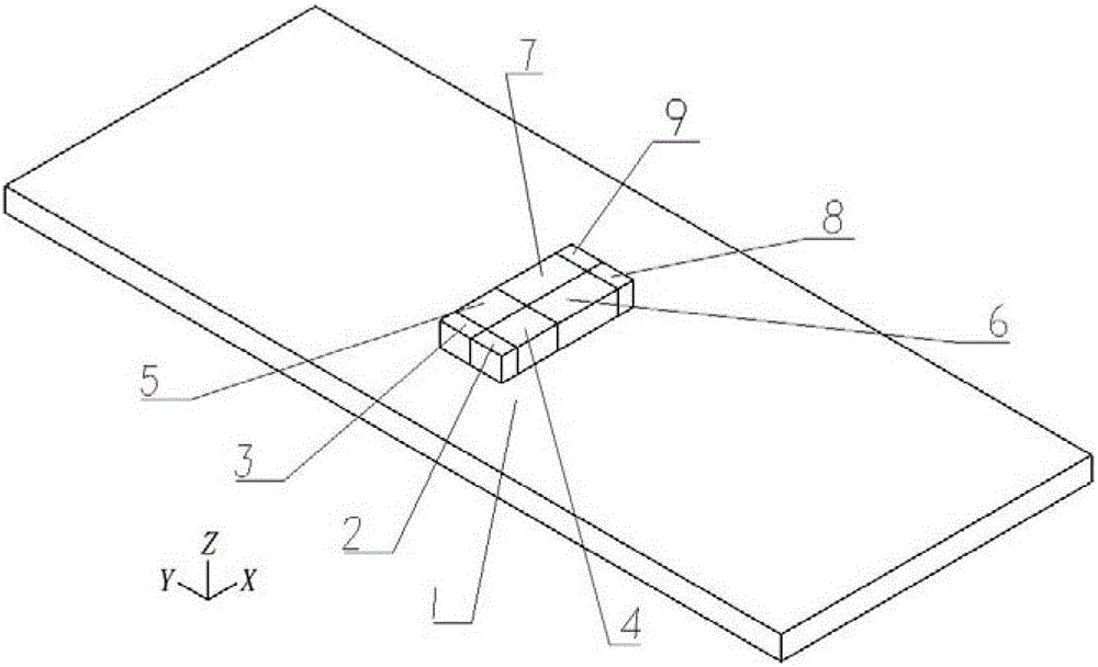
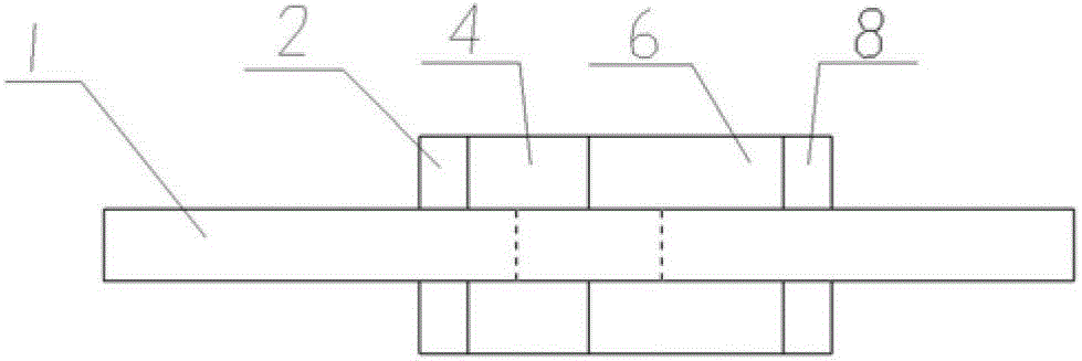
[0039] Taking a rectangular plate with a circular through hole as an example, three-dimensional penetrating cracks are established on both sides of the hole. The size of the rectangular plate is 100×40×3mm, the through hole is located in the center of the rectangle, and the radius is 3mm; the lengths of the penetrating cracks on the sides of the holes are 2mm and 5mm respectively.

[0040] Step 1 Create a structural solid model

[0041] (1) Create a rectangular plate with a length of 100mm, a width of 40mm, and a height of 3mm;

[0042] (2) At the center of the plate, build a cylinder penetrating the plate with a radius of 3mm and a height of 10mm along the direction perpendicular to the plate;

[0043] (3) By applying Boolean operations and subtracting the cylinder from a rectangular plate, a solid model of a rectangular plate with a circular through hole can be established, ...

Embodiment 2

[0063] Example 2: Modeling of three-dimensional penetrating cracks on one side of a spot-faced hole

[0064] Countersink holes are often used as countersunk rivet holes, which are very common in aircraft structures and are a typical variable-section hole. Taking a rectangular plate with a spot-faced hole as an example, a three-dimensional penetrating crack is established on one side of the hole. The size of the rectangular plate is 100×40×3mm, the spot facing hole is located in the center of the rectangle, the hole radius is 2mm, the spot spot radius is 3mm, and the spot spot depth is 1mm; the length of the penetrating crack on one side of the hole is 5mm.

[0065] Step 1 Create a structural solid model

[0066] (1) Create a rectangular plate with a length of 100mm, a width of 40mm, and a height of 3mm;

[0067] (2) At the center of the plate, build a cylinder penetrating the plate with a radius of 2mm and a height of 10mm along the direction perpendicular to the plate;

[...


PUM


Abstract

The invention discloses a hole edge three-dimensional crack modeling method based on finite element software. The method includes the following steps: step A1, crack body generating; step A2, crack surface generating; and step A3, grid sweeping: grid division is carried out on the outer surface of the crack body, singularity of a crack tip end of the outer surface is defined, then, a divided surface grid is swept along the direction of a crack tip end line, and grid division of the whole crack body can be finished. All the adopted modeling methods such as solid building, size overlapping and the grid sweeping are universal methods and can be used in most commercial finite element software, and universality is strong in actual operation; and the whole train of modeling thought of the hole edge three-dimensional crack modeling method based on the finite element software can be used for building hole edge three-dimensional cracks of various holes such as round holes, square holes and dimple holes in various structure types such as plane structures, curved surface structures and combined structures, and the university in application fields is strong.

Description

technical field [0001] The invention relates to a damage tolerance analysis method, and in particular provides a finite element software-based modeling method for a three-dimensional penetrating crack at the side of a through hole and a modeling method for a three-dimensional penetrating crack at the side of a variable-section hole. Background technique [0002] Damage tolerance is an engineering science that studies the design criteria, analysis methods and test techniques of structures containing cracks, with the purpose of preventing catastrophic failure of structures due to cracks. The design and analysis method of damage tolerance is widely used in the aviation field, and it is an important technical means to ensure flight safety. The analysis methods of damage tolerance include numerical analysis and experimental research, and the modeling and analysis of structures with cracks using finite element software is the main way of numerical analysis. Through finite element...

Claims


Application Information

Patent Timeline
Patent Type & Authority Patents(China)
IPC IPC(8): G06F17/50
Inventor 何宇廷张腾崔荣洪安涛张海威高潮丁华邵青侯波伍黎明
Owner 空军工程大学
Why Eureka
Try Eureka