Pipe bending apparatus

A bending processing and bending technology, which is applied in the field of bending processing devices, can solve the problems of unusability and inability to correct the rotation angle, and achieve the effects of good precision, easy shape change, and reliable precision

Active Publication Date: 2013-05-22
SANOH IND CO LTD
View PDF6 Cites 12 Cited by
  • Summary
  • Abstract
  • Description
  • Claims
  • Application Information

AI Technical Summary

Problems solved by technology

[0005] However, in the pipe rotation assembly disclosed in Japanese Patent Application Laid-Open No. 2005-52854 described above, since the cam grooves are formed by cutting, adjustment such as correction of the rotation angle of the pipe cannot be performed. In this case, Necessity to create new cam grooves
In addition, since the cam groove is a dedicated groove shape, it cannot be used for other pipes with different curved shapes.

Method used


Image

  • Pipe bending apparatus
  • Pipe bending apparatus
  • Pipe bending apparatus

Examples


Embodiment Construction

[0034] Hereinafter, the present invention will be described in detail based on an illustrated embodiment.

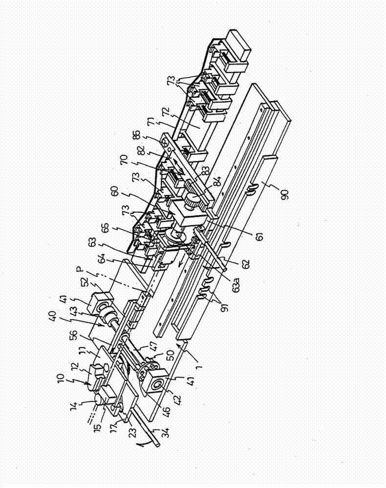
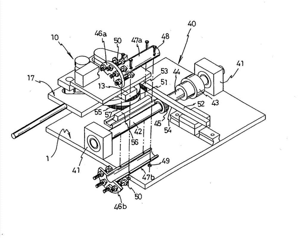
[0035] The illustrated pipe bending device includes a bending unit 10 that bends a pipe P at a predetermined angle, a transport unit 60 that supports and advances the pipe P, and a rotation unit 70 that rotates the pipe P by a predetermined amount.

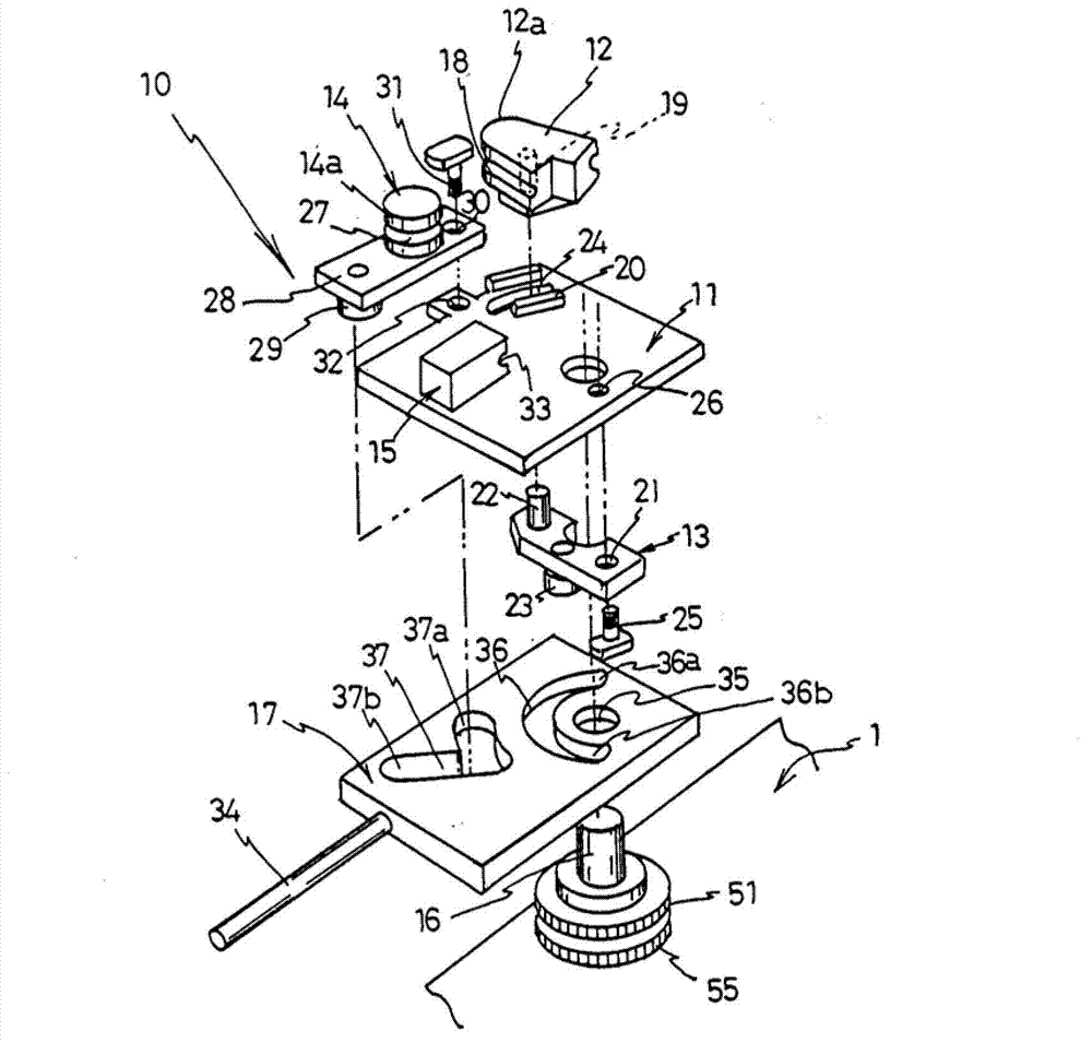
[0036] In the bending unit 10 , a substrate 11 is provided above the device frame 1 with an appropriate gap therebetween. On the substrate 11, as figure 2 As shown, a bending die 12 , a bending die work piece 13 , a presser 14 , and a clamping device 15 are respectively provided, and a shaft 16 is rotatably supported between the frame 1 and the base plate 11 . Furthermore, one end portion of the operation plate 17 is integrally provided on the shaft 16 .

[0037] The bending die 12 has a partially arc-shaped peripheral surface 12a, and an arc-shaped groove 18 having a substantially semicircular cross-section for housing t...


PUM


Abstract

The purpose of the present invention is to provide a pipe bending apparatus comprising a turning means that can be easily implemented at low cost and can be used for bending pipes in different directions and in different shapes. In order to achieve this purpose, in the pipe bending apparatus of the present invention, a pipe feeding base (61) is disposed so as to be movable in the feeding direction of a pipe (P), a feeding means (60) is configured by rotatably disposing a chuck (63) on the feeding base to support the pipe, a cam (71) formed by bending a long plate or rod is disposed substantially parallel with the movement direction of the feeding base, a cam follower (86) is disposed on the feeding base so as to be movable in a direction perpendicular to the axis of the pipe, a turning means (70); is configured by engaging the cam follower with the cam and also connecting the cam follower to the chuck, and, together with an operation which moves the feeding base forward, the cam follower follows the cam and moves, and the motion of the cam follower is transmitted to the chuck so as to turn the chuck.

Description

technical field [0001] The present invention relates to a pipe bending device. More specifically, it relates to a pipe bending device suitable for manually bending a pipe. Background technique [0002] For example, a fuel supply pipe of an automobile must be arranged in a limited space in a narrow engine room. Therefore, it is necessary to arrange the pipes by bending them at predetermined angles in different predetermined directions. [0003] Such a device for bending a tube includes a tube transport unit that holds the tube and advances the tube by a predetermined amount, a tube rotation unit that rotates the tube by a predetermined amount, and a tube that bends the tube at a predetermined length position. The bending assembly bends the pipe at a predetermined position of the pipe at a predetermined angle, and then, the conveying assembly advances the pipe by a predetermined amount, and the rotating assembly rotates the pipe by a predetermined amount, and the bending ass...

Claims


Application Information

Patent Timeline
Patent Type & Authority Applications(China)
IPC IPC(8): B21D7/025
CPCB21D7/025
Inventor 兰光平中里和彦
Owner SANOH IND CO LTD
Why Eureka
Try Eureka