
Exhaust gas treatment unit for an exhaust gas recirculation line

A technology for waste gas treatment and pipelines, which is used in waste gas recirculation, exhaust devices, engine components, etc., and can solve problems such as large costs and complex flanges/collars.

Inactive Publication Date: 2013-05-22
EMITEC GESELLSCHAFT FUR EMISSIONSTECHNOLOGIE MBH
View PDF4 Cites 0 Cited by
  • Summary
  • Abstract
  • Description
  • Claims
  • Application Information

AI Technical Summary

Problems solved by technology

However, the production of such flanges/collars is so complex that

Method used


Image

  • Exhaust gas treatment unit for an exhaust gas recirculation line
  • Exhaust gas treatment unit for an exhaust gas recirculation line
  • Exhaust gas treatment unit for an exhaust gas recirculation line

Examples


Embodiment Construction

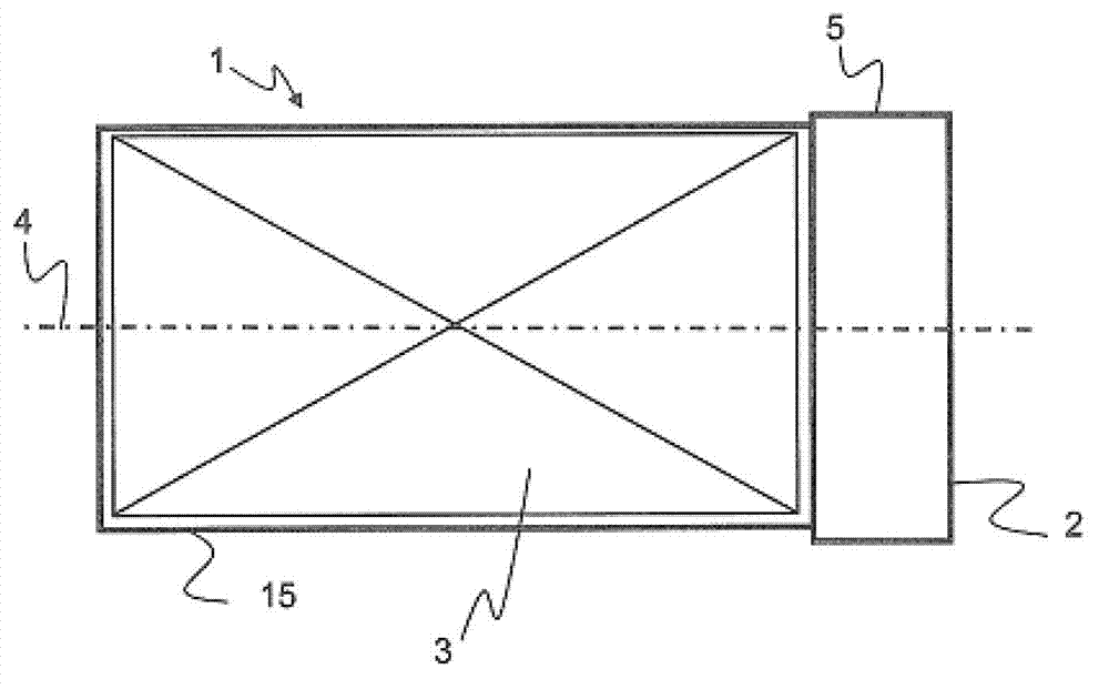
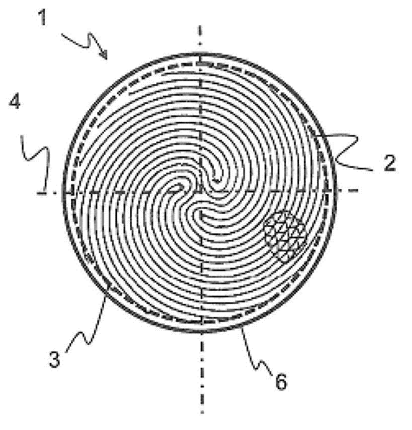
[0048] figure 1 Shown is an exhaust gas treatment unit 1 with a housing 15 and a (single) exhaust gas treatment body 3 , also with a pinch region 5 on one open side 2 and with a main axis 4 . The pressing area 5 is concentric with the main axis of the exhaust gas treatment body 3 and also has a step with respect to the exhaust gas treatment body 3 . figure 2 shows a plan view of the open side 2 of the exhaust gas treatment unit 1, or figure 1 The compression region 5 in the cross-section 6 of the exhaust gas treatment body 3 . It can be seen here that the cross section 6 corresponds to the shape of the exhaust gas treatment body 3 . Representatively shown here is a structure comprising alternating corrugated and smooth foils wound in an S-shape in a variety of honeycomb structures.

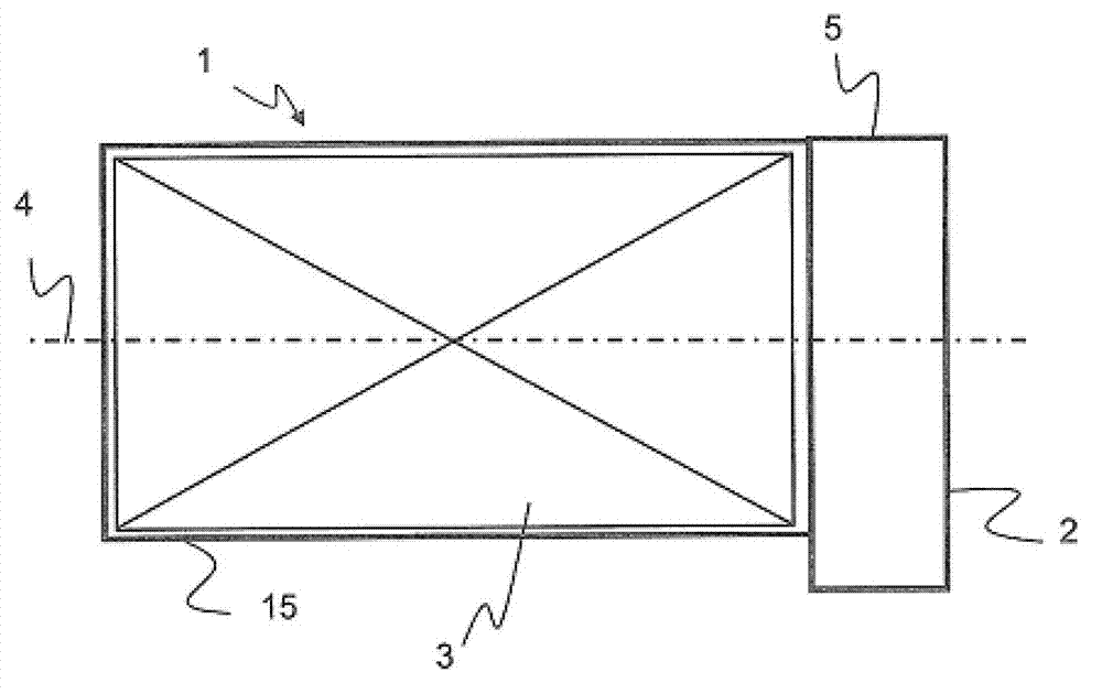
[0049] image 3 Shown is an exhaust gas treatment unit 1 with an exhaust gas treatment body 3 and an extrusion region 5 which is placed on the open side 2 of the exhaust gas treatment unit 1 ...


PUM


Abstract

The invention relates to an exhaust gas treatment unit (1), comprising a substantially cylindrical exhaust gas treatment body (3) having a main axis (4) and, on at least one opening side (2) of the exhaust gas treatment unit (1), at least one of the following connecting means: an offset compression zone (5), and a molded structure (16) for positive engagement. Moreover, the invention relates to an internal combustion engine (11) having at least one (such) exhaust gas treatment unit (1), comprising at least one exhaust gas conducting line (7) and at least one exhaust gas treatment unit (1), which is completely introduced in the at least one exhaust gas conducting line (7).

Description

technical field [0001] The invention relates to an exhaust gas treatment unit for an internal combustion engine, in particular a catalytic converter substrate integrated into an exhaust gas recirculation line (EGR line) of a motor vehicle engine. The invention also proposes an internal combustion engine with an integrated exhaust gas treatment unit. Background technique [0002] It is already known that there is a need to purify the exhaust gases of mobile internal combustion engines of undesired components that cause health problems and / or are harmful to the environment, in particular so that they also meet the emission requirements of future legal regulations. In particular, this purpose requires improved systems for exhaust gas treatment so that existing engine concepts can be easily adapted to future exhaust gas purification objectives. Likewise, continuous efforts are being made to integrate the exhaust gas treatment units required for this purpose in vehicles in a par...

Claims


Application Information

Patent Timeline
IPC IPC(8): F01N3/28F01N13/18
CPCF01N2350/00F01N2450/02F01N3/2842F02M25/0718F02M25/074F01N13/1838F01N2450/20F01N3/10F01N13/18B01D53/94Y02T10/121F01N3/28F01N3/2839F02M26/15F02M26/35Y02A50/20
Inventor 卡斯滕·克鲁斯戈特弗里德·威廉·海兹曼恩布鲁诺·克拉韦茨
Owner EMITEC GESELLSCHAFT FUR EMISSIONSTECHNOLOGIE MBH
Features
  • Generate Ideas
  • Intellectual Property
  • Life Sciences
  • Materials
  • Tech Scout
  • Unparalleled Data Quality
  • Higher Quality Content
  • 60% Fewer Hallucinations
Learn More