
Thickness controller of cast-in-place concrete floor and method thereof

A concrete and controller technology, applied in construction, building structure, construction material processing and other directions, can solve the problems of large thickness error of floor slab and inability to control the thickness of concrete by pulling wires, and achieves convenient production, convenient intuitive detection, and simple use. Effect

Active Publication Date: 2013-05-29
SHANGHAI ZHONGJIN CONSTR GRP
View PDF6 Cites 8 Cited by
  • Summary
  • Abstract
  • Description
  • Claims
  • Application Information

AI Technical Summary

Problems solved by technology

[0003] The technical problem to be solved by the present invention is to provide a cast-in-place concrete floor slab thickness controller and its method, which can solve the defect in the prior art that the thickness error of the floor slab is controlled by drawing a white line on the slab side formwork or column inserting reinforcement, As well as the difficulty of controlling the thickness of the concrete by pulling wires due to the arching of the center of the beam and slab in the long-span beam-slab structure

Method used


Image

  • Thickness controller of cast-in-place concrete floor and method thereof
  • Thickness controller of cast-in-place concrete floor and method thereof

Examples


Embodiment Construction

[0020] Below in conjunction with specific embodiment, further illustrate the present invention. It should be understood that these examples are only used to illustrate the present invention and are not intended to limit the scope of the present invention. In addition, it should be understood that after reading the teachings of the present invention, those skilled in the art can make various changes or modifications to the present invention, and these equivalent forms also fall within the scope defined by the appended claims of the present application.

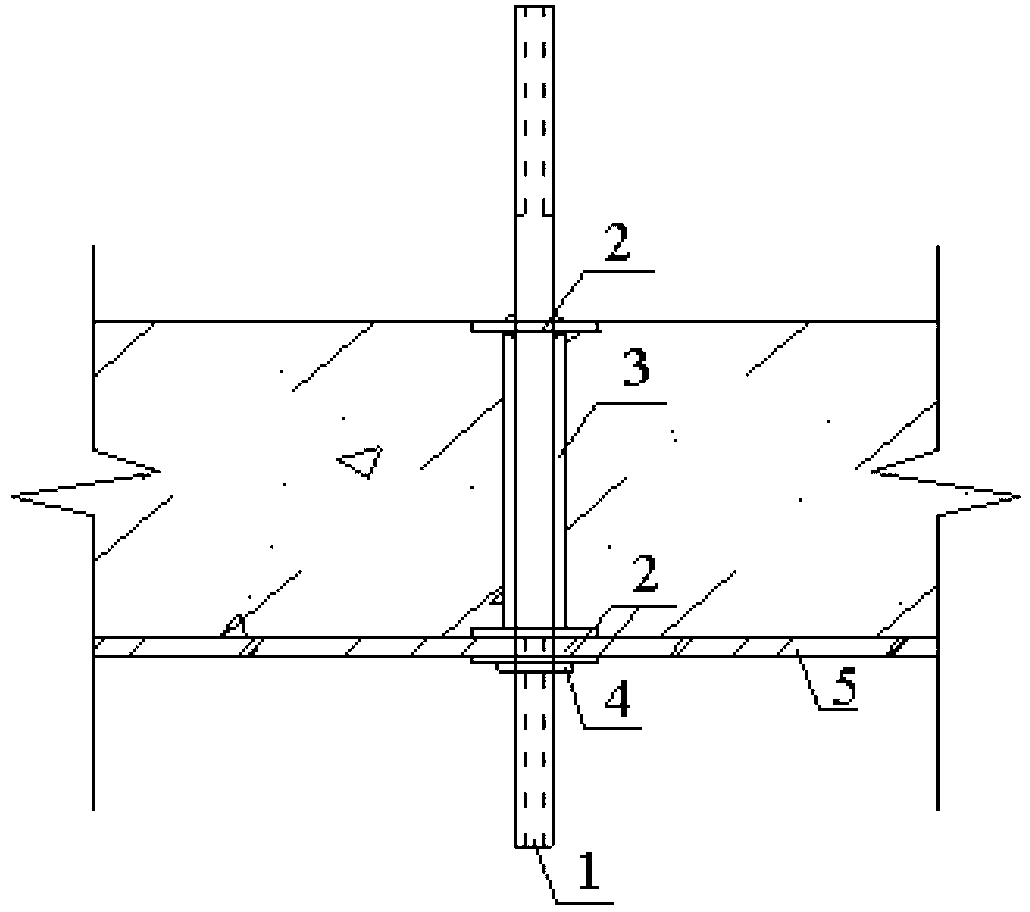
[0021] The invention relates to a cast-in-place concrete floor thickness controller, such as figure 1 As shown, it includes a round steel 1, a steel gasket 2 and a casing 3, and the two ends of the round steel 1 are threaded; there are three steel gaskets on the round steel, and one of them is a fixed steel gasket located on the round steel In the middle part, the other two pieces are movable steel gaskets, which are respectiv...


PUM


Abstract

The invention relates to a thickness controller of a cast-in-place concrete floor and a method of the thickness controller of the cast-in-place concrete floor. The controller comprises round steel, steel cushion slices and a sleeve pipe. Two ends of the round steel are threaded. Three steel cushion slices are arranged on the round steel, wherein one slice is a fixed steel cushion slice and the other two slices are movable steel cushion slices which are respectively arranged on upper and lower surfaces of a template. The sleeve pipe is arranged between the fixed steel cushion slice and the movable steel cushion slices and sleeved on the round steel. The method of the thickness controller of the cast-in-place concrete floor includes the following steps. A twist drill is used for drilling a hole in a plate bottom template before the concrete is cast. The sleeve pipe is cut and then sleeved on the round steel, and a steel cushion slice is sleeved on the round steel again. The round steel penetrates the hole in the plate bottom template. A steel cushion slice is additionally arranged below the plate bottom template and screwed tightly through a screw nut. In time of casing with concrete, an upper surface of the steel cushion slice welded above the round steel is used as panel elevation control. After the concrete is congealed, the round steel is removed. A sleeve pipe hole is used as a detection hole of thickness of a floor when an entity is detected. The thickness controller of the cast-in-place concrete floor and the method of the thickness controller of the cast-in-place concrete floor can control all sorts of plates with thickness ranging from 80mm to 320mm.

Description

technical field [0001] The invention relates to the field of concrete floor slabs in the technical field of construction, in particular to a controller for the thickness of cast-in-place concrete floor slabs and a method thereof. Background technique [0002] In construction engineering, the thickness of the cast-in-place concrete floor slab is controlled by copying the elevation and drawing the white line on the side formwork of the slab or the column inserting reinforcement. Since the workers have to continuously use the ruler to control the concrete during the pouring process, the operation is cumbersome and the error It is also large, especially in the construction of long-span beam-slab structures, due to the arching in the center of the beam, it is impossible to pull wires to control the thickness of the concrete, resulting in insufficient concrete thickness at the arching part. Contents of the invention [0003] The technical problem to be solved by the present inve...

Claims


Application Information

Patent Timeline
Patent Type & Authority Applications(China)
IPC IPC(8): E04G21/10
Inventor 冯永刚
Owner SHANGHAI ZHONGJIN CONSTR GRP
Learn More