Supercharge Your Innovation With Domain-Expert AI Agents!

Compression apparatus

一种压缩装置、压缩机的技术,应用在用于弹性流体的泵送装置的部件、发动机功能、发动机控制等方向,能够解决耗电变大、噪音变大等问题

Active Publication Date: 2013-05-29
KOSCO COMPRESSOR CO LTD
View PDF7 Cites 7 Cited by
  • Summary
  • Abstract
  • Description
  • Claims
  • Application Information

AI Technical Summary

Problems solved by technology

In addition, if the fan with a large capacity is operated at its maximum capacity in order to sufficiently cool all the devices, there is a problem that power consumption also increases.
Furthermore, since a large-capacity fan is operated, the noise becomes louder

Method used


Image

  • Compression apparatus

Examples


Embodiment Construction

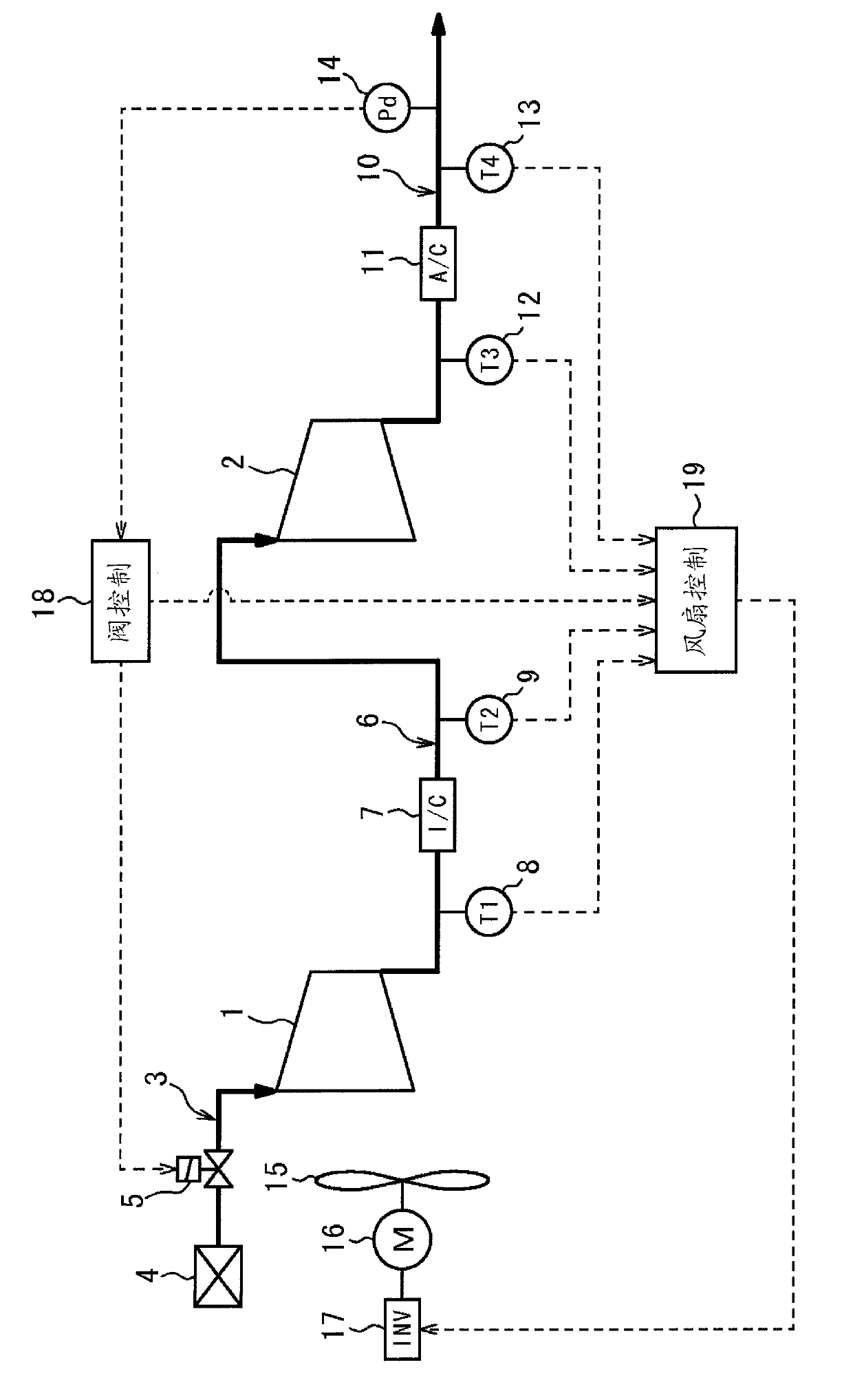
[0016] Thus, embodiments of the present invention will be described with reference to the drawings. exist figure 1 A compressing device according to an embodiment of the present invention is shown in . The compression device of the present embodiment is a device for producing compressed air, and includes a first compressor 1 and a second compressor 2 connected in series.

[0017] A suction filter 4 and a suction regulating valve 5 are provided in a suction flow path 3 for supplying air to the first compressor 1 . An intercooler 7 is provided in the intermediate flow path 6 connecting the first compressor 1 and the second compressor 2, and a first temperature detector for detecting the temperature of air discharged from the first compressor 1 is provided upstream of the intercooler 7. 8. A second temperature detector 9 that detects the temperature of the air supplied to the second compressor 2 downstream of the intercooler 7 . An aftercooler 11 is provided in the discharge p...


PUM


Abstract

Provided is a compression apparatus for cooling multiple devices using a single fan with a small amount of electric power. An upper limit temperature, a first gain applied in a case in which a suction adjustment valve is opened, and a second gain applied in a case in which the suction adjustment valve is closed are set in advance for each of multiple temperature detectors provided at different locations of the compression apparatus; and, for each of the multiple temperature detectors, a difference between a detected value and the upper limit temperature is calculated, and a rotation speed of the fan is determined based on the smallest value in the differences, and the first gain or the second gain set for the temperature detector having the smallest difference.

Description

technical field [0001] The invention relates to a compression device. Background technique [0002] As a compression device for compressing gas, a compressor and an aftercooler and other accessories are housed inside a package (casing), and a compression device having a fan for cooling each device is widely used. In such a compression device, generally, not only the compressor but also the intercooler and aftercooler are cooled by a single fan (see Japanese Patent No. 3773443 and Japanese Patent No. 4418321). [0003] In a compression device that cools a plurality of devices with a single fan, a fan with a large capacity is often installed in order to sufficiently cool all the devices even under the worst conditions. In addition, if the fan with a large capacity is operated at the maximum capacity in order to sufficiently cool all the devices, there is a problem that power consumption also increases. Furthermore, since a large-capacity fan is operated, noise also becomes l...

Claims


Application Information

Patent Timeline
Patent Type & Authority Applications(China)
IPC IPC(8): F04B39/06F04B39/00F04D27/00
CPCF04D27/003F04D29/5826F04B39/00F04D27/00F04B39/06F04B39/066F04D29/58F04D15/0022F04D15/0263F05D2260/211F05D2260/213F05D2270/112F05D2270/3013
Inventor 平田和也
Owner KOSCO COMPRESSOR CO LTD
Features
  • R&D
  • Intellectual Property
  • Life Sciences
  • Materials
  • Tech Scout
  • Unparalleled Data Quality
  • Higher Quality Content
  • 60% Fewer Hallucinations
Learn More