
Straight line cutting anastomat

A straight-line cutting and stapler technology, applied in the field of medical devices, can solve the problems of the device not firing, only firing, and surgery failure, etc., and achieve the effect of improving firing accuracy, reducing requirements, and reducing the risk of surgery

Active Publication Date: 2013-06-05
CHANGZHOU HEALTH MIRCROPORT MEDICAL DEVICE
View PDF5 Cites 11 Cited by
  • Summary
  • Abstract
  • Description
  • Claims
  • Application Information

AI Technical Summary

Problems solved by technology

The firing structure of the linear cutting stapler in the traditional mechanical stapler is directly pushed by the human hand to complete the firing action. This method has extremely high requirements for the user (skills and hand strength). Poor mastery of skills and strength can easily cause the instrument to fire or only fire halfway, which will eventually lead to the failure of the operation, and the risk is extremely high

Method used


Image

  • Straight line cutting anastomat
  • Straight line cutting anastomat
  • Straight line cutting anastomat

Examples


Embodiment Construction

[0015] In order to make the content of the present invention easier to understand clearly, the present invention will be described in further detail below according to specific embodiments in conjunction with the accompanying drawings,

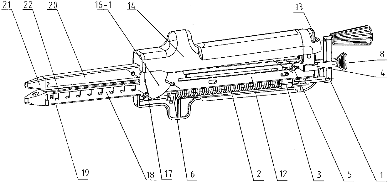
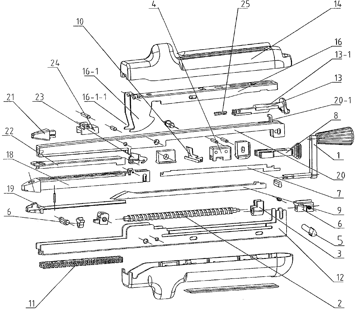
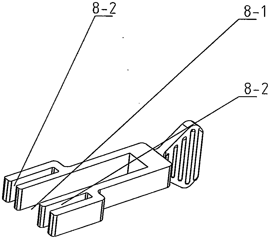
[0016] Such as Figure 1~2 As shown, a linear cutting stapler includes a staple cartridge assembly, an abutment seat assembly, an assembly seat frame 12, a locking lever assembly and a firing mechanism for actuating the staple cartridge assembly, and the anvil seat assembly is detachably installed on the assembly seat On the frame 12, the nail cartridge assembly is installed in the assembly seat frame 12, and one end of the locking rod assembly is hinged on the nail abutment seat assembly, and the firing mechanism includes a push block 4, a cutter bar 7, a wedge 9, a screw rod 2, and a drive nut 3 1. Rotate the handle 1 and the screw fixing seat 6, the screw fixing seat 6 is fixedly connected to the bottom of the assembly seat frame 12, the tw...


PUM


Abstract

The invention discloses a straight line cutting anastomat which comprises a nail cabin component, a nail seat abutting component, a component seat support, a locking lever component and a trigger mechanism used for driving the nail seat abutting component to move. The trigger mechanism comprises a pushing block, a cutter bar, an inclined wedge, a screw rod, a transmission nut, a rotary handle and a screw rod fixing seat. The screw rod fixing seat is fixedly connected with the bottom of the component seat support. Two ends of the screw rod respectively and rotationally support on the screw rod fixing seat. The rotary handle is connected with one end of the screw rod in an inserting mode. The cutter bar and the inclined wedge are respectively arranged on the pushing block. The pushing block is installed in the component seat support in a sliding mode. The pushing block is fixedly connected with the transmission nut. A screw nut pair is composed of the transmission nut and the screw rod. According to the straight line cutting anastomat, a traditional pushing type trigger principle is changed and rotary force is changed to pushing force, trigger force is stable so that requirements for a user are greatly reduced, accuracy of trigger is improved, operation risk in the process of an operation is greatly reduced and safety in the process of the whole operation is improved.

Description

technical field [0001] The invention relates to a linear cutting stapler, which belongs to the field of medical instruments. Background technique [0002] At present, the disposable linear cutter and stapler is used in general surgery, thoracic surgery, gynecology and pediatrics, and its main purpose is to cut, resect and anastomose tissues. The product is composed of an abutment part and a staple cartridge part. Its working principle is: push the firing button, move inside the staple cartridge through the inclined wedge, and the inclined wedge drives the push piece to push the staples out of the surface of the staple cartridge until they are formed. The firing structure of the linear cutting stapler in the traditional mechanical stapler is directly pushed by the human hand to complete the firing action. This method has extremely high requirements for the user (skills and hand strength). Poor mastery of skills and strength can easily cause the instrument to fire or only fir...

Claims


Application Information

Patent Timeline
Patent Type & Authority Applications(China)
IPC IPC(8): A61B17/072
CPCA61B17/07207
Inventor 施志文
Owner CHANGZHOU HEALTH MIRCROPORT MEDICAL DEVICE
Learn More