Bridge type stone cutter with polishing function

A stone cutting machine, grinding and polishing technology, applied in grinding/polishing equipment, grinding machines, manufacturing tools, etc., can solve the problem of not having the ability to grind and polish stone, and it is urgent to improve processing efficiency, save labor costs, and reduce moving procedures. Effect

Active Publication Date: 2013-06-05
福建省南安市巨轮机械有限公司
View PDF7 Cites 10 Cited by
  • Summary
  • Abstract
  • Description
  • Claims
  • Application Information

AI Technical Summary

Problems solved by technology

[0002] As known, the bridge-type stone cutter mainly includes a beam, two longitudinal beams, a movable seat (middle drag body), a lifting frame, a workbench and a cutting device arranged on the lifting frame; the beam is erected between the two longitudinal beams, A longitudinal movement mechanism is installed between the beam and the longitudinal beam, and the moving seat is set on the cross beam so that it can move horizontally. A transverse moving mechanism is installed between the moving seat and the beam. There is a lifting and moving mechanism between the moving seat and the cutting device. The cutting device includes a knife rest arranged at the lower end of the lifting frame, a main shaft horizontally arranged on the knife rest along the longitudinal direction, a circular saw blade arranged on the main shaft, and a drive shaft connected by a belt and a pulley. Rotating main motor, the existing bridge-type stone cutter only has the function of cutting stone, and does not have the function of grinding and polishing stone. In stone processing, cutting and polishing are often two processes next to each other. Therefore, the design A bridge-type stone cutter integrating cutting, grinding and polishing has become urgent

Method used


Image

  • Bridge type stone cutter with polishing function
  • Bridge type stone cutter with polishing function
  • Bridge type stone cutter with polishing function

Examples


Embodiment Construction

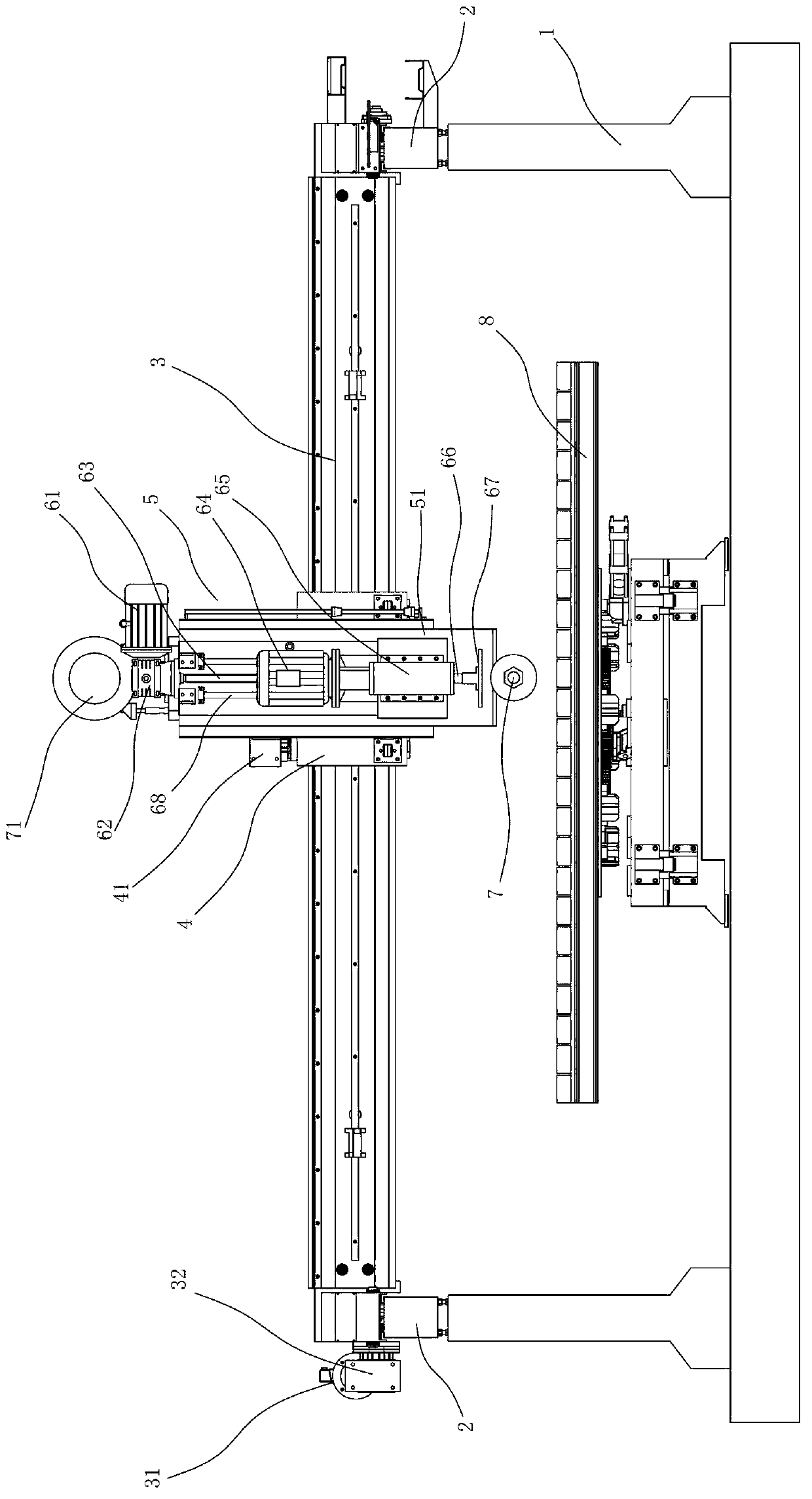
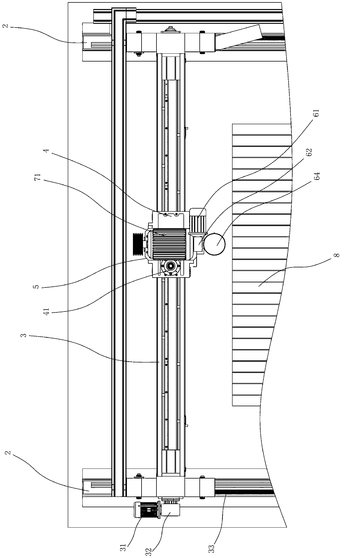
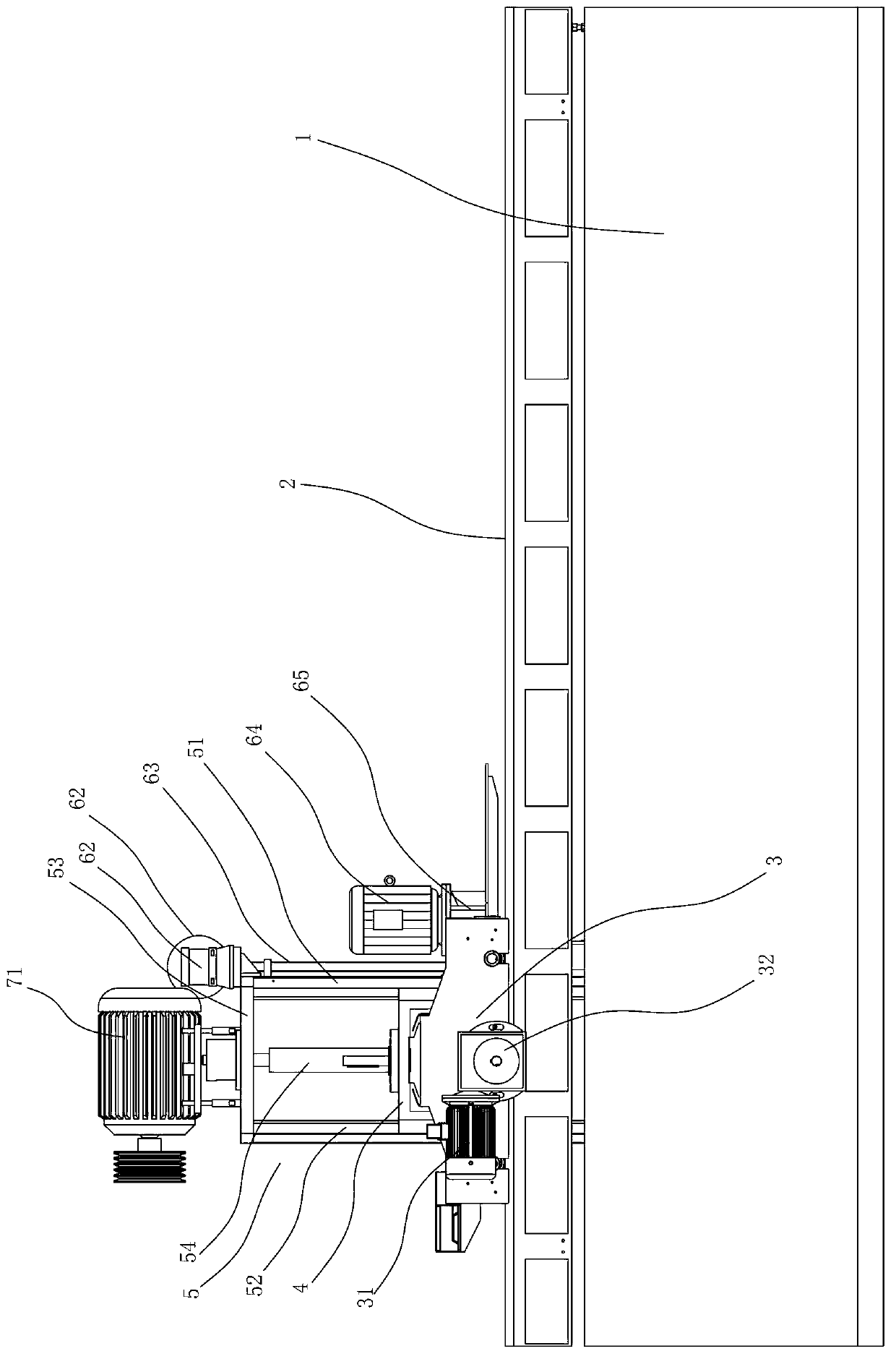
[0016] refer to figure 1 , figure 2 and image 3 As shown, a bridge-type stone cutter with grinding and polishing functions includes a cement foundation 1, two longitudinal beams 2 arranged on the cement foundation 1 at intervals in the transverse direction, a crossbeam 3 erected between the two longitudinal beams 2, and a laterally movable ground The moving base 4 arranged on the beam 3, the elevating frame 5 arranged on the moving base 4 that can be moved up and down, the workbench 8, the cutting device arranged on the elevating frame 5, the The longitudinal movement mechanism, the transverse movement mechanism 41 arranged between the moving base 4 and the crossbeam 3, the lifting movement mechanism arranged between the lifting frame 5 and the moving base 4, the grinding and polishing device arranged on the lifting frame 4 and respectively Control devices connected with various mechanisms and devices.

[0017] The lifting movement mechanism is an oil cylinder 54 vertical...


PUM


Abstract

A bridge type stone cutter with a polishing function comprises a crossbeam, two longitudinal beams, a moving seat, a lifting frame, a worktable and a cutting device. The cutting device is arranged on the lifting frame, a longitudinal moving mechanism is arranged among the crossbeam and the longitudinal beams, a transverse moving mechanism is arranged between the moving seat and the crossbeam, and a lifting moving mechanism is arranged between the lifting frame and the moving seat. The bridge type stone cutter is characterized by further comprising a polishing device, the polishing device is arranged on the lifting frame and comprises a spindle box, a spindle, a main motor, an abrasive disc and a vertical moving mechanism, the spindle box is arranged on the lifting frame in such a manner that the spindle box can vertically move up and down on the lifting frame, the spindle is vertically arranged on the spindle box, the main motor is arranged on the spindle box and is connected with the spindle to drive the spindle to rotate, the abrasive disc is arranged at the lower end of the spindle, and the vertical moving mechanism is connected with the spindle box to drive the spindle box to vertically move. The bridge type stone cutter has the advantages that a cutting function is integrated with the polishing function, a procedure for shifting stone between cutting equipment and polishing equipment and a procedure for clamping the stone are omitted, the stone processing efficiency is improved, and the labor cost is saved.

Description

technical field [0001] The invention relates to the field of stone processing machinery, in particular to a bridge-type stone cutter. Background technique [0002] As known, the bridge-type stone cutter mainly includes a beam, two longitudinal beams, a movable seat (middle drag body), a lifting frame, a workbench and a cutting device arranged on the lifting frame; the beam is erected between the two longitudinal beams, A longitudinal movement mechanism is installed between the beam and the longitudinal beam, and the moving seat is arranged on the cross beam so that it can move horizontally. A transverse moving mechanism is installed between the moving seat and the cross beam. There is a lifting and moving mechanism between the moving seat and the cutting device includes a knife rest set at the lower end of the lifting frame, a main shaft horizontally set on the knife rest along the longitudinal direction, a circular saw blade set on the main shaft, and a drive shaft connecte...

Claims


Application Information

Patent Timeline
Patent Type & Authority Applications(China)
IPC IPC(8): B28D1/04B24B19/22
Inventor 蔡建华高河森许金灿赵晶
Owner 福建省南安市巨轮机械有限公司
Why Eureka
Try Eureka