
Airless tire

A technology of airless tires and outer belts, applied to non-pneumatic tires, tire parts, wheels, etc., can solve the problems of reducing driving performance and achieve the effect of improving uniformity and radial runout performance

Active Publication Date: 2013-06-05
HANKOOK TIRE WORLDWIDE
View PDF11 Cites 49 Cited by
  • Summary
  • Abstract
  • Description
  • Claims
  • Application Information

AI Technical Summary

Problems solved by technology

This deformation of the outer belt is the cause of noise, vibration, etc., which degrades driving performance

Method used


Image

  • Airless tire
  • Airless tire
  • Airless tire

Examples


Embodiment Construction

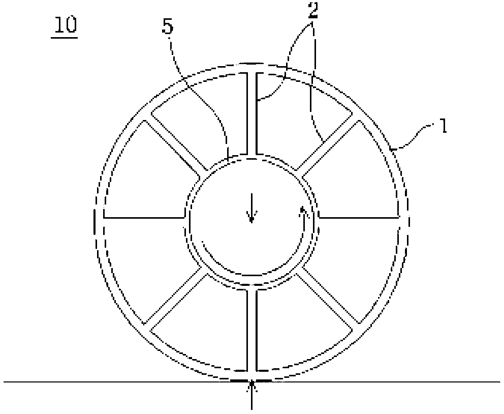
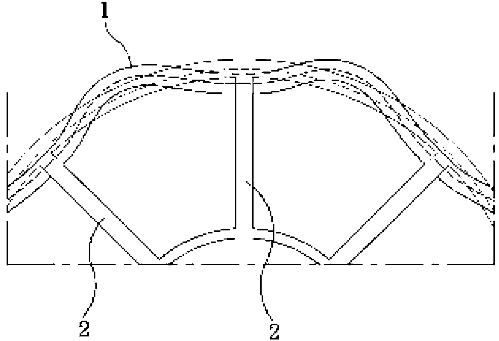
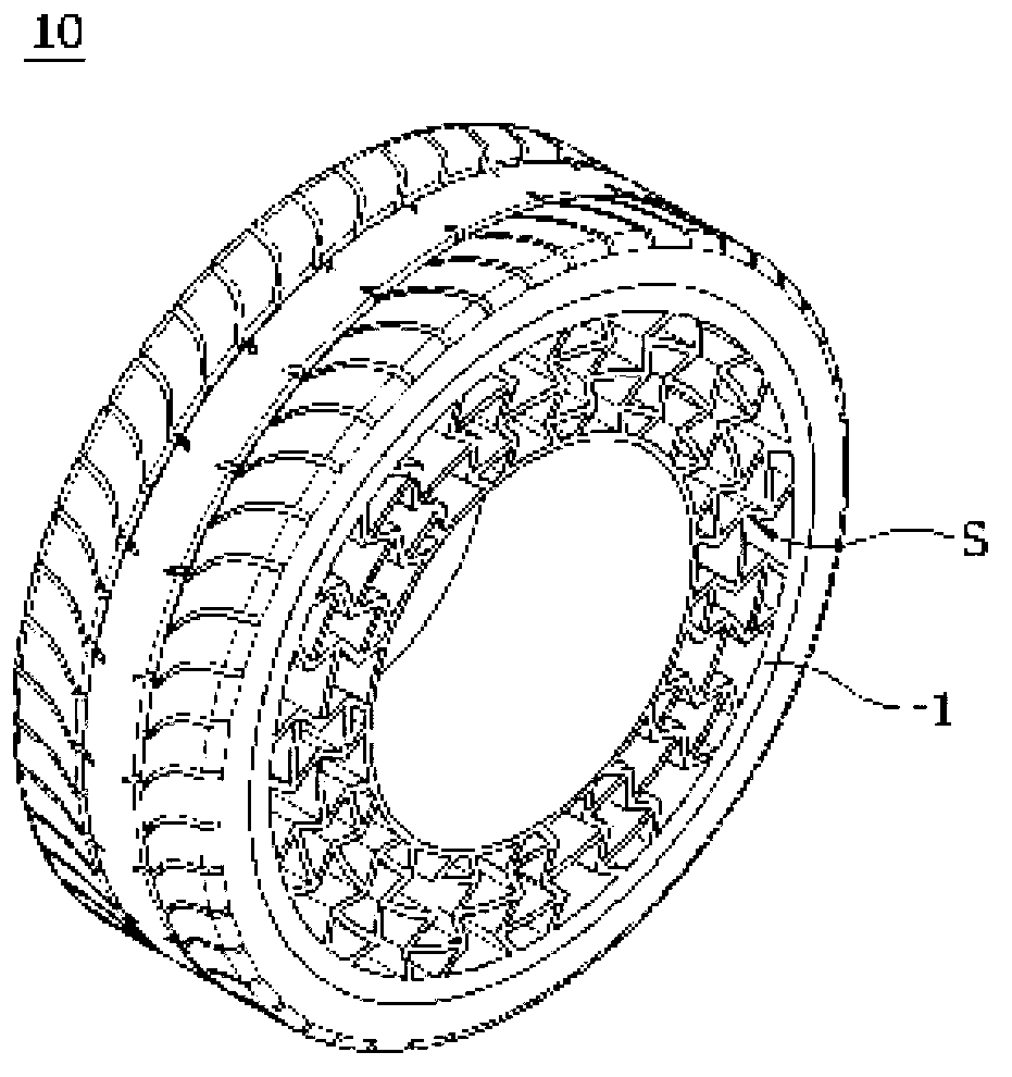
[0034] An airless tire according to the present invention includes an outer belt and a structure provided inside the outer belt. The structure is formed in the radial direction of the tire and includes a plurality of spokes attached to the inner side of the outer belt. Depending on the design of the airless tire, the shape and number of spokes can be changed in various ways.

[0035] The outermost spokes of the structure are connected to the inner side of the outer band. At this time, in order to increase the contact area between the spoke and the outer band, a leg portion is formed at the connection portion between the spoke and the outer band. By further forming the foot portion, the influence of the stress formed on the spoke on the inner surface of the outer band can be reduced. The pedestal portions may be manufactured separately from the spokes and then bonded or welded to the junctions of the spokes and the outer straps. Furthermore, the foot part can be manufactured...


PUM


Abstract

The present invention relates to an airless tire which supports load by an internal structure of the tire, comprising: an outboard tire; a plurality of spokes connected to the inside surface of the outboard tire; and a column foot for increasing the contact area of the spokes and the outboard tire. Therefore, localized bending deformation caused by the stress formed by the spokes can be prevented, uniformity of the airless tire can be improved, and the radial run-out performance is improved.

Description

technical field [0001] The present invention relates to an airless tire (Airless Tire) in which a working load is supported by a structure inside the tire instead of compressed air. Background technique [0002] Tires are components that are mounted on automobiles, airplanes, trucks, etc. and roll in contact with the ground. Tires must not only bear the load of vehicles and airplanes to be transported, but also cushion the impact of running on uneven ground. [0003] Widely used rubber tires include solid tires used in low-speed and heavy-load environments, pneumatic tires widely used in automobiles and the like, recently developed airless tires, and the like. [0004] Pneumatic tires are tires that inject compressed air into a closed space to maintain the shape of the tire and obtain cushioning performance by air pressure. Compared with solid tires, they have the advantages of light weight and excellent cushioning performance. However, pneumatic tires suffer from difficul...

Claims


Application Information

Patent Timeline
IPC IPC(8): B60B9/26
CPCB60C7/08B60B1/0261B60C7/107
Inventor 金用勋金相协
Owner HANKOOK TIRE WORLDWIDE
Learn More