Oscillating-buoy wave power device with hinged angle slide bar

A wave energy and float technology, which is applied in the field of floating wave energy power generation devices, can solve the problems of poor wave adaptability of floats, cable entanglement and damage, maintenance and repair difficulties, etc. The effect of drag and drop

Active Publication Date: 2013-06-05
GUANGZHOU INST OF ENERGY CONVERSION - CHINESE ACAD OF SCI
View PDF8 Cites 8 Cited by
  • Summary
  • Abstract
  • Description
  • Claims
  • Application Information

AI Technical Summary

Problems solved by technology

The existing buoy devices have the following disadvantages that cannot be igno

Method used


Image

  • Oscillating-buoy wave power device with hinged angle slide bar
  • Oscillating-buoy wave power device with hinged angle slide bar

Examples


Embodiment 1

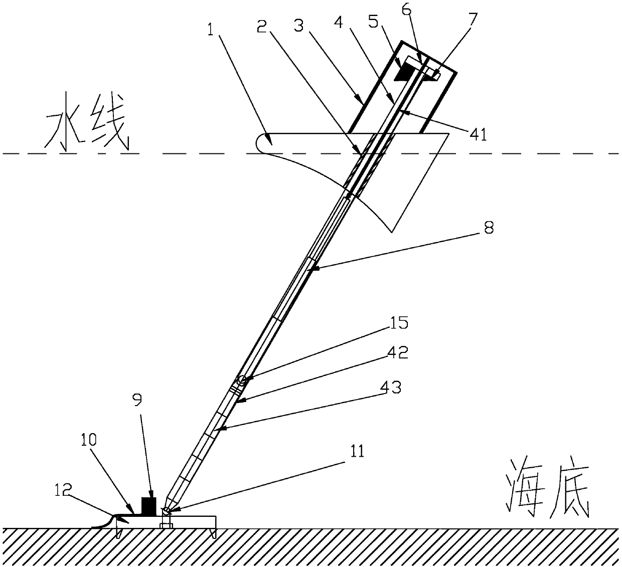
[0041] see figure 1 As shown, the wave energy device with oscillating buoy with hinged inclined slide bar includes an underwater appendage 12, a float 1, an energy conversion system 9 is arranged on the platform of the underwater appendage 12, and a linear bearing is installed on the central axis of the float 1 2. It also includes a sliding rod 4 with a hydraulic cylinder 8 inside. The sliding rod 4 forms an angle of less than 90 degrees with the horizontal line. The upper end of the sliding rod 4 is equipped with a gantry 3. The gantry 3 is connected with a pull rod 41, and the pull rod 41 extends into the slide. The rod 4 is connected with the rod end of the hydraulic cylinder 8, and the rodless end of the hydraulic cylinder 8 is installed on the platform vertical to the center line of the hydraulic cylinder 8 in the slide rod 4 through the hinge point 15, and the center line of the hydraulic cylinder 8 is connected to the center line of the slide rod 4 The center line coinc...

Embodiment 2

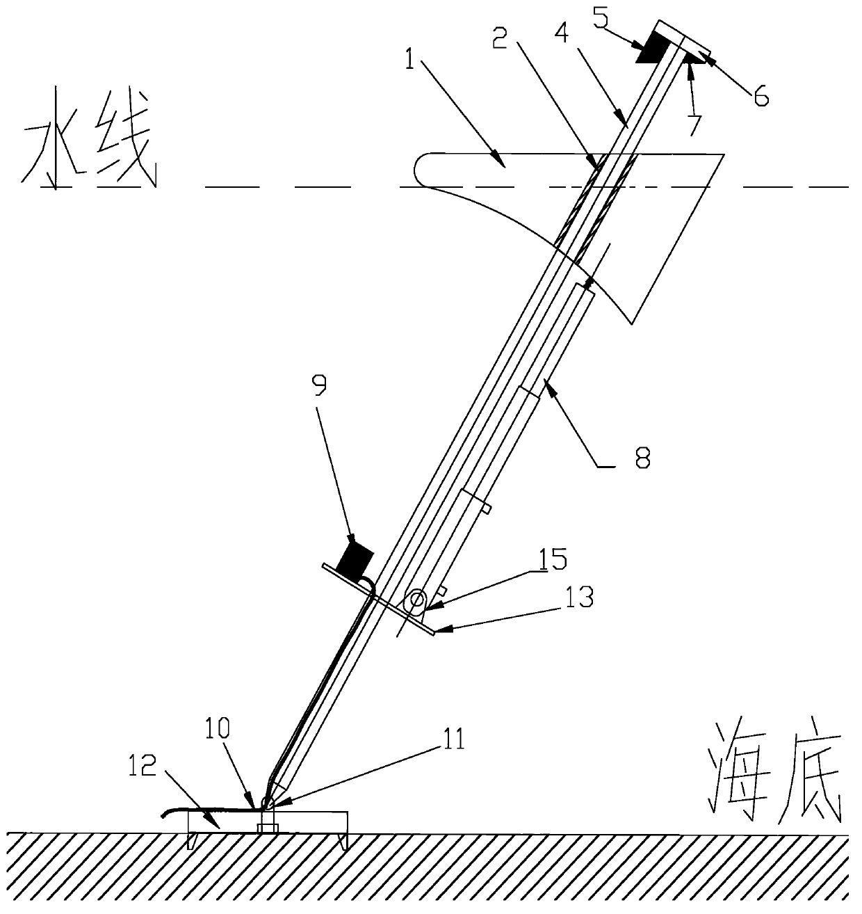
[0048] Such as figure 2 As shown, the difference between this embodiment and the first embodiment is that another linking method is adopted between the float 1 and the hydraulic cylinder 8, and the working principle is the same as that of the first embodiment. figure 2 Among them, a hydraulic cylinder 8 (which may be a multi-stage hydraulic cylinder) is installed on the platform 13 and beside the slide bar 4, the bottom end of the hydraulic cylinder 8 is connected to the platform 13 through a hinge point 15, and the top end of the hydraulic cylinder 8 is connected to the float 1 , the hydraulic cylinder 8 and the sliding rod 4 are in a parallel position, the hydraulic cylinder 8 is connected to the energy conversion system 9 through a hydraulic pipe; the energy conversion system 9 is connected to a cable 10, and the cable 10 falls directly from the underwater appendage 12 to the seabed and leads to the shore . With the axis of the slide bar 4 as the center, multiple hydraul...


PUM


Abstract

The invention discloses an oscillating-buoy wave power device with a hinged angle slide bar. The oscillating-float wave power device comprises an underwater attachment, a float, an energy conversion system and a slide bar. A portal frame is arranged at the upper end of the slide bar. A pull bar is connected inside the portal frame and extends into the slide bar to be connected with a rod end of a hydraulic cylinder. A rodless end of the hydraulic cylinder is mounted on a platform which is located inside the slide bar and perpendicular to a center line of the hydraulic cylinder, and the center line of the hydraulic cylinder is overlapped with that of the slide bar. A buoy is connected with the hydraulic cylinder through the pull bar. The slide bar penetrates through axis of the buoy by a linear bearing. The buoy is able to slide on the slide bar freely with no resistance. A seal block for sealing an inner cavity of the slide bar is disposed at the top end of the slide bar, one surface of the seal block, facing the buoy, is provided with a limit block and an anti-impact block respectively, the lower end of the slide bar is mounted on a universal hinge, the universal hinge is mounted on the underwater hinge, and a hydraulic pipe of the hydraulic cylinder penetrates the universal hinge to be connected inside the energy conversion system along the inner wall of the slide bar. The energy conversion system is connected with a cable, and the cable directly falls to sea bed and leads to a bank from the underwater attachment.

Description

technical field [0001] The invention relates to a floating wave energy generating device, in particular to an oscillating buoy wave energy device with hinged oblique sliding rods. Background technique [0002] Oscillating buoy wave energy devices are usually composed of relatively moving buoys, anchor chains, hydraulic or power generation devices, and use the heave motion of the buoy in the waves to absorb wave energy. The lower device has higher primary conversion efficiency. The existing buoy devices have the following disadvantages that cannot be ignored: the buoy has poor adaptability to waves; the structure is easily damaged; the cable is entangled and damaged; the mooring is complicated, the anchor chain is under a large force; Contents of the invention [0003] The object of the present invention is to overcome the technical problems existing in the prior art and provide a novel floating wave energy generating device. [0004] In order to achieve the above purpose...

Claims


Application Information

Patent Timeline
IPC IPC(8): F03B13/14
CPCY02E10/38Y02E10/30
Inventor 游亚戈张亚群王文胜盛松伟吝红军
Owner GUANGZHOU INST OF ENERGY CONVERSION - CHINESE ACAD OF SCI
Why Eureka
Try Eureka