Diversion damper slowly-closed check valve

A check valve and damping technology, which is applied in the field of water supply pipeline control valves, can solve the problems that the valve cannot be closed slowly, affects the normal operation of the valve, and the valve flow coefficient is small, so as to reduce parts, facilitate installation and layout, and prolong the service life Effect

Active Publication Date: 2013-06-05
WUHAN DAYU VALVE
View PDF11 Cites 0 Cited by
  • Summary
  • Abstract
  • Description
  • Claims
  • Application Information

AI Technical Summary

Problems solved by technology

[0002] Existing check valves used in large water delivery pipelines over 1 meter include butterfly check valves. The disc of this structure requires external power when closing, and the structural layout is relatively troublesome. In addition, when the disc rotates to close, Vibration will be generated due to the action of water flow, which will affect the normal operation of the valve
There is an existing

Method used


Image

  • Diversion damper slowly-closed check valve
  • Diversion damper slowly-closed check valve
  • Diversion damper slowly-closed check valve

Examples


Embodiment 1

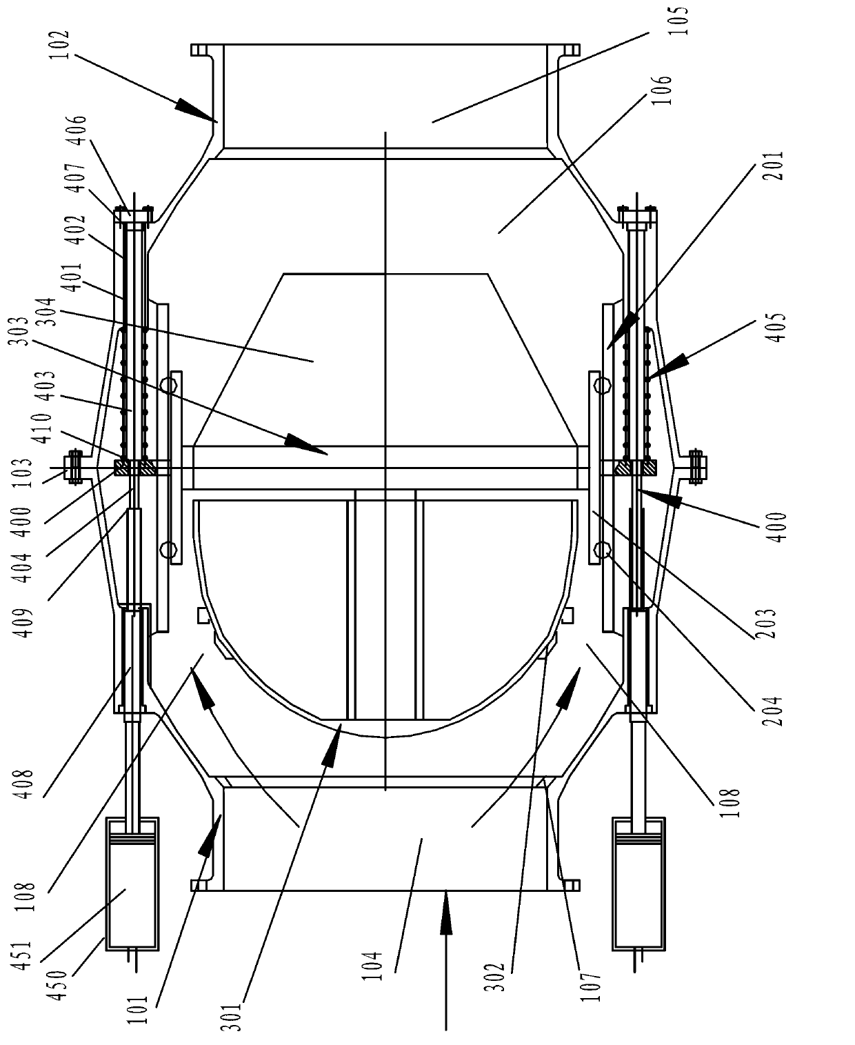
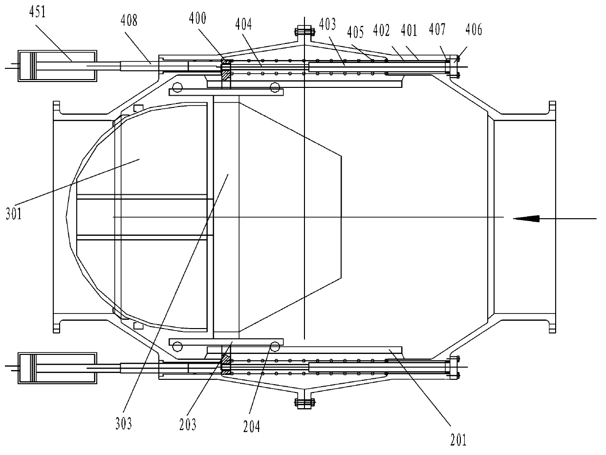
[0037] Such as figure 1 , 2 As shown, the valve body includes a front valve body 101 and a rear valve body 102 , and the front valve body 101 and the rear valve body 102 are connected and sealed by a flange structure 103 provided on the front valve body 101 and the rear valve body 102 . The front valve body 101 includes a facility medium (water) inlet conduit section 104 at the front end, and the rear valve body 102 includes a facility medium (water) outlet conduit section 105 at the rear end. The rear end of the front valve body 101 and the front section of the rear valve body 102 form an installation cavity 106 of the valve internal structure.

[0038] Check direction of the valve body In this embodiment, a valve seat 107 is provided at the end of the medium (water) entering conduit section 104 of the valve body 101 in this embodiment.

[0039] The installation cavity 106 is provided with a supporting mobile structure. In this embodiment, according to the pipe diameter and...

Embodiment 2

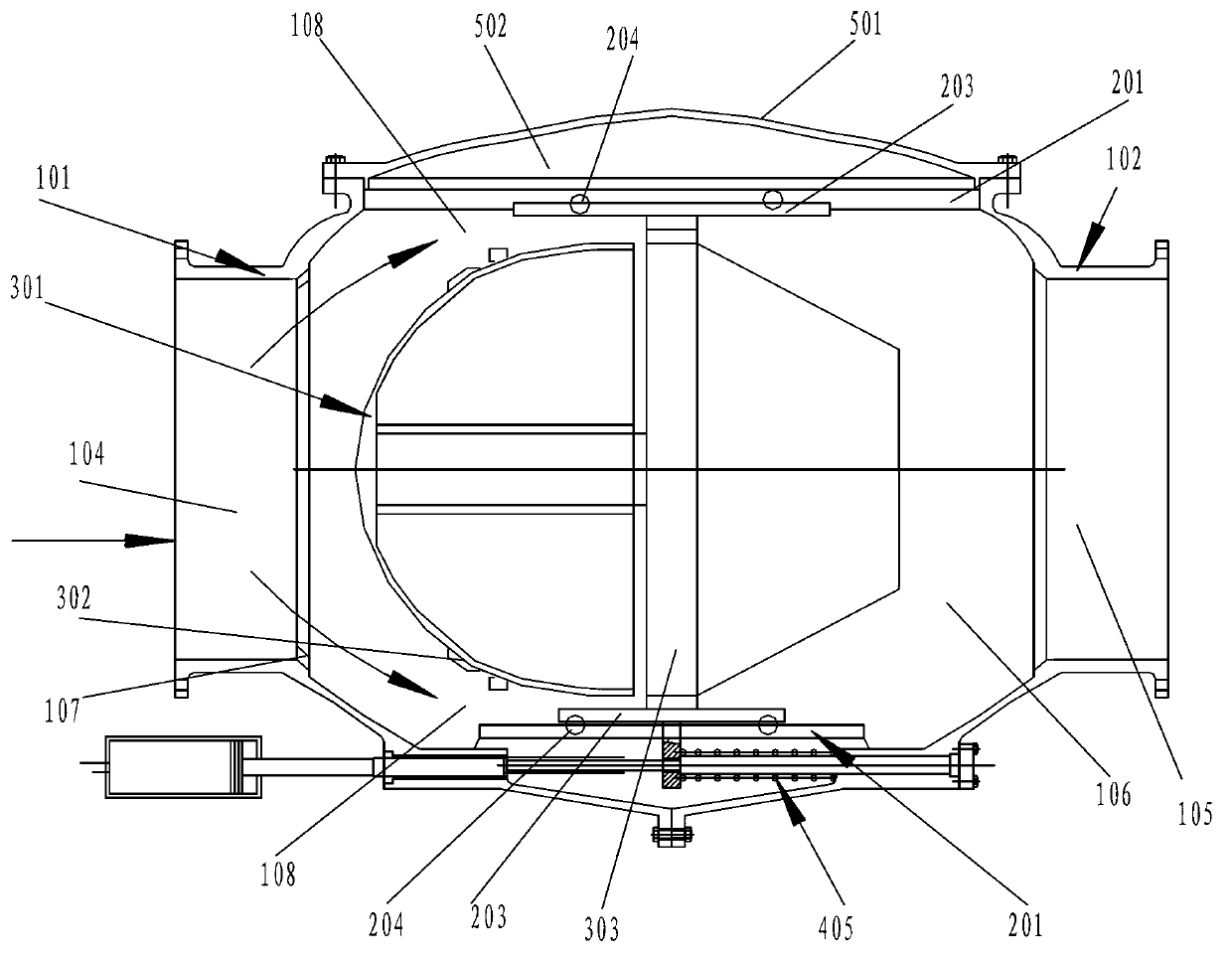
[0052] Such as image 3 As shown, the valve body is provided with an installation hole 501 of the valve body structure, and the installation hole is connected and sealed with the valve cover 502; Form a diversion channel. The shape formed by the inner wall of the valve body shell and the inner wall of the bonnet at the guide channel corresponds to the shape of the check valve core of the guide body, which is a part of an ellipsoid shape; or is formed by tangency of multiple arc segments The shape of the rotating body; or the rotating body formed by the tangency of multiple arc segments, the shape formed by the end of the rotating body tangent to the cylinder or the frustum of the cone; or the shape of the spherical crown; or the shape of the spherical crown and the A shape formed tangentially to a cylinder or frustum of a cone. The structure in the valve body is the same as that in Embodiment 1, and will not be repeated here.

[0053] The working principle of the large-diam...


PUM


Abstract

The invention discloses a diversion damper slowly-closed check valve which comprises a valve body provided with medium circulation tubes at two ends. A valve seat is arranged in the valve body. The diversion damper slowly-closed check valve further comprises a diversion body check valve core arranged in the valve body, a support moving structure for supporting the diversion body check valve core, a sliding block connected with the diversion body check valve core, a sliding rod connected with the sliding block, and a non-return driving structure with one end contacted with the sliding block and used for driving the sliding block to perform non-return movement. The other end of the sliding rod is connected with a moving damper structure. The diversion body check valve core in the diversion damper slowly-closed check valve adopts a movable structure, namely the diversion effect and the sealing effect are played, the whole structure is convenient to install, the support moving structure is used for supporting the diversion body check valve core, the supporting is stable, and operation is stable. The moving damper structure can produce resistance to movement of the sliding block and the diversion body check valve core, quick movement is avoided, and dismantle of a pipeline water hammer and protection of a pipeline and a water pump are achieved through slow closing.

Description

technical field [0001] The invention belongs to a water supply pipeline control valve, in particular to a pipeline check valve in a large pipeline. Background technique [0002] Existing check valves used in large water delivery pipelines over 1 meter include butterfly check valves. The disc of this structure requires external power when closing, and the structural layout is relatively troublesome. In addition, when the disc rotates to close, Due to the action of water flow, vibration will be generated, which will affect the normal operation of the valve. There is an existing quick-closing check valve, the valve disc moves in a fixed guide body, and the movement guide structure of the valve disc is inconvenient to install. At the same time, the flow coefficient of the valve is small, and the water loss is relatively large during the process of water passing through the valve through the pipeline; at the same time , the valve of the above structure cannot realize slow closin...

Claims


Application Information

Patent Timeline
IPC IPC(8): F16K15/02F16K47/00
Inventor 李习洪何锐
Owner WUHAN DAYU VALVE
Why Eureka
Try Eureka