Liquid ethane conveying pipeline pressure protection system and method

A technology for transmission pipelines and protection systems, applied in pipeline systems, gas/liquid distribution and storage, mechanical equipment, etc., can solve problems such as increased pipeline costs, increased difficulty and cost of storage tank manufacturing, and few researches on water hammer release , to achieve the effect of eliminating fire prevention, saving manpower, and eliminating water hammer overpressure

Pending Publication Date: 2018-07-24
CHINA PETROLEUM ENG & CONSTR +1
View PDF0 Cites 5 Cited by
  • Summary
  • Abstract
  • Description
  • Claims
  • Application Information

AI Technical Summary

Problems solved by technology

[0005] For liquid ethane pipelines, the above two pressure protection methods have their own disadvantages: for the method of water hammer relief valve and storage tank, in view of the high saturated vapor pressure of liquid ethane at room temperature, the storage tank needs to be designed under pressure In principle, this increases the difficulty and cost of storage tank manufacturing, and also poses a challenge to the safety of storage tanks in remote areas; for the method of pipeline strength protection, as mentioned above, correct judgment of extreme pressure is the premise to ensure pipeline safety, and for For large-diameter pipes, increasing the design pressure may lead to a substantial increase in pipe costs
[0006] At present, there are very few special water hammer release studies on liquid ethane pipeline transportation, reasonable water hammer control methods need to be explored in depth, and at the same time, measures to prevent overpressure caused by the temperature of such a medium with high expansibility also need to be developed

Method used


Image

  • Liquid ethane conveying pipeline pressure protection system and method
  • Liquid ethane conveying pipeline pressure protection system and method

Examples


Embodiment Construction

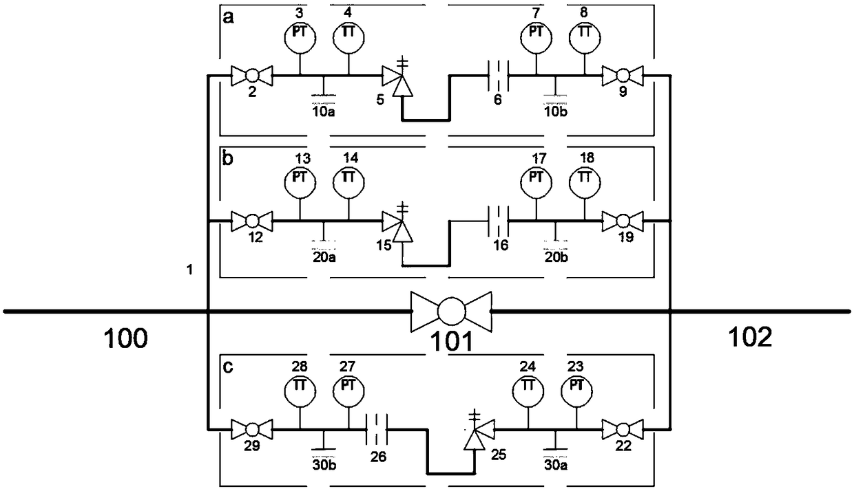
[0031] A liquid ethane pipeline pressure protection system, such as figure 1 As shown, it includes: bypass nipple 1, ball valve 2, pressure transmitter 3, temperature transmitter 4, positive pressure relief valve 5 in the first column, flow limiting orifice plate 6, pressure transmitter 7, temperature Transmitter 8, ball valve 9, drain valve group 10, ball valve 12, pressure transmitter 13, temperature transmitter 14, positive second column pressure relief valve 15, flow limiting orifice 16, pressure transmitter 17. Temperature transmitter 18, ball valve 19, drain valve group 20, ball valve 22, pressure transmitter 23, temperature transmitter 24, reverse pressure relief valve 25, flow limiting orifice 26, pressure transmitter 27. Temperature transmitter 28, ball valve 29, drain valve group 30.

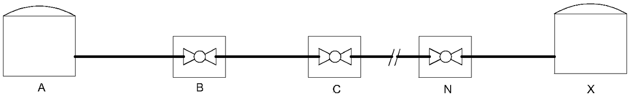
[0032] The schematic diagram of the pressure protection of the whole system of the liquid ethane delivery pipeline of the present invention is as follows figure 2 As shown, such for...


PUM


Abstract

The invention discloses a liquid ethane conveying pipeline pressure protection system and method. The system comprises forward pressure relief systems and reverse pressure relief systems which are arranged in parallel on trunk line pumps or valve bypasses. According to the system and the method, the pump or valve front pressure increment caused by action of the pumps or trunk line valves in a liquid ethane pipeline or the isolation section pressure increment caused by temperature rise is automatically released into adjacent upstream and downstream trunk lines by stimulating relief devices arranged on the pumps of the valve bypassed so as to prevent overpressure mediums from entering the atmosphere and limit the highest operating pressure of each pipe section. The system and the method havethe advantages that the water hammer overpressure problem under transient operation of a pipeline can be solved, the influence on the strength of the pipeline due to the volume change caused by influence of the temperature of the mediums after shutdown of the pipeline can be avoided, the overpressure mediums are not discharged from the system after being released, and therefore the investment ofaccessory facilities are reduced, and the safety, environmental protection and energy conservation effects can be achieved.

Description

technical field [0001] The invention relates to a pressure protection system and method for a liquid ethane delivery pipeline. Background technique [0002] In recent years, the oil and gas exploration and petrochemical industries have developed rapidly, the condensate gas fields have been vigorously developed, the extraction technology of natural gas auxiliary products has been continuously developed, and the sources, processing and sales of natural gas liquids (NGL) have increased day by day. [0003] The chemical composition of liquid ethane is mainly methane, ethane and propane, among which the mole fraction of ethane can reach about 95%. A typical liquid ethane mixture has a very low bubble point (<-80°C, under normal pressure), and a critical temperature of about 25-35°C, so it is very easy to vaporize after leakage. Liquid ethane has a large latent heat of evaporation and absorbs a large amount of heat when volatilized, which may easily cause frostbite to people i...

Claims


Application Information

Patent Timeline
Patent Type & Authority Applications(China)
IPC IPC(8): F17D3/01
CPCF17D3/01
Inventor 陈俊文谌贵宇刘玉峰郭艳林王磊昝林峰边云燕陈彰兵汤晓勇缪晖陈海鹏胡连锋李巧马艳琳汤智昀李小丽彭方宇向熠星
Owner CHINA PETROLEUM ENG & CONSTR
Why Eureka
Try Eureka