Safe and reliable shock mitigation system for new-energy automobile

A new energy vehicle and shock absorption system technology, applied in shock absorbers, springs/shock absorbers, cleaning methods using tools, etc., can solve the influence of hydraulic oil circulation, the use of hydraulic shock absorbers, and the force of oil holes. Deformation and other problems to achieve the effect of reducing the probability of cylinder explosion, improving safety and reliability, and improving practicability and reliability

Active Publication Date: 2018-08-17
HUNAN KANGDEJIA FORESTRY TECH CO LTD
View PDF5 Cites 8 Cited by
  • Summary
  • Abstract
  • Description
  • Claims
  • Application Information

AI Technical Summary

Problems solved by technology

[0003] But the existing hydraulic shock absorber still has some deficiencies in the process of actual use. For example, the working principle of the existing hydraulic shock absorber is that when there is relative motion due to vibration between the vehicle frame and the axle, the hydraulic shock absorber will The piston moves up and down, and the oil in the shock absorber cavity repeatedly flows from one cavity through different oil holes into another cavity. At this time, the friction between the hole wall and the oil and the internal friction between the oil molecules affect the vibration. The damping force is formed to convert the vibration energy of the car into oil heat energy, which is then absorbed and dissipated into the atmosphere by the shock absorber. However, in some bad road conditions

Method used


Image

  • Safe and reliable shock mitigation system for new-energy automobile
  • Safe and reliable shock mitigation system for new-energy automobile
  • Safe and reliable shock mitigation system for new-energy automobile

Examples


Embodiment Construction

[0027] The present invention is described in further detail now in conjunction with accompanying drawing. These drawings are all simplified schematic diagrams, and only illustrate the basic structure of the present invention in a schematic manner, so they only show the configurations related to the present invention.

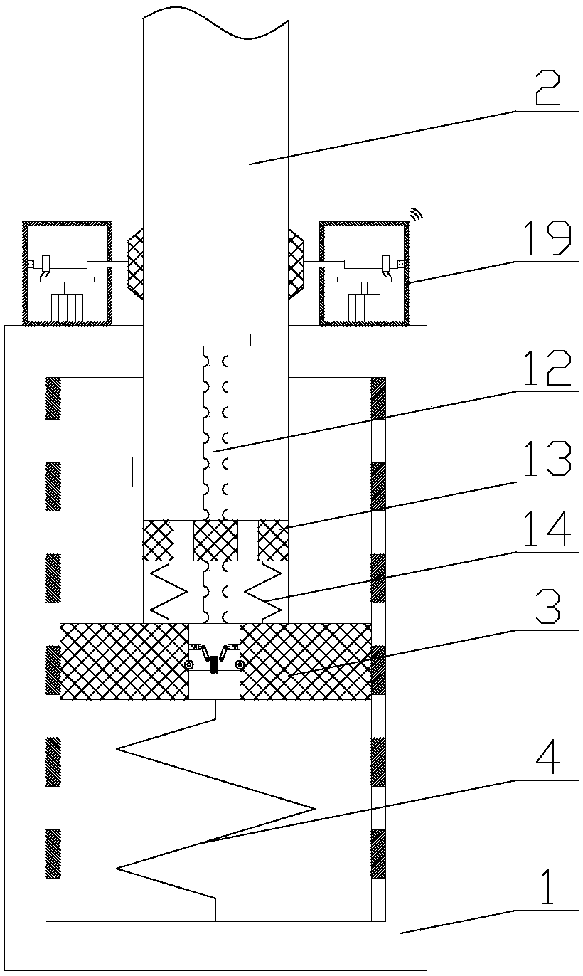
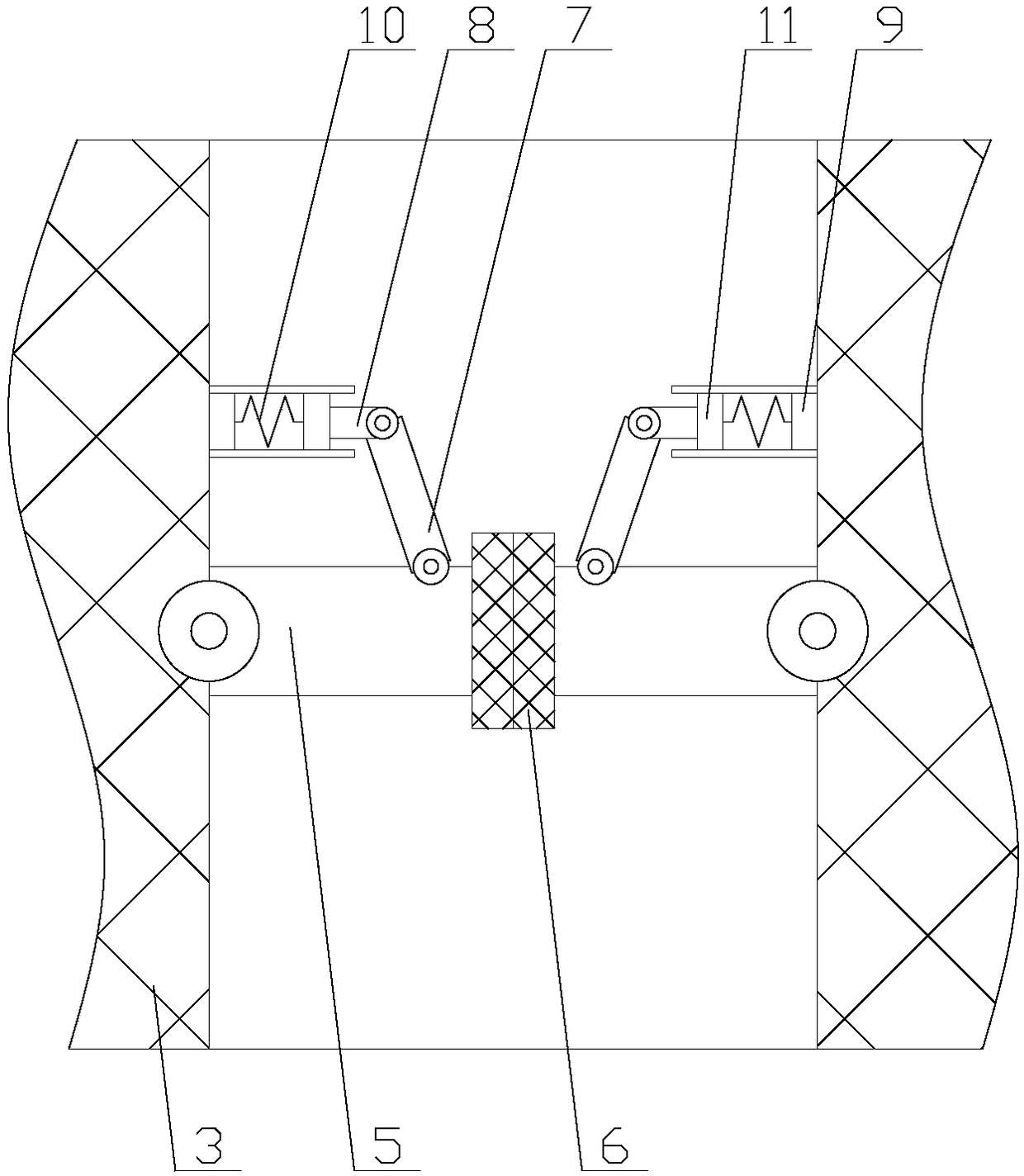
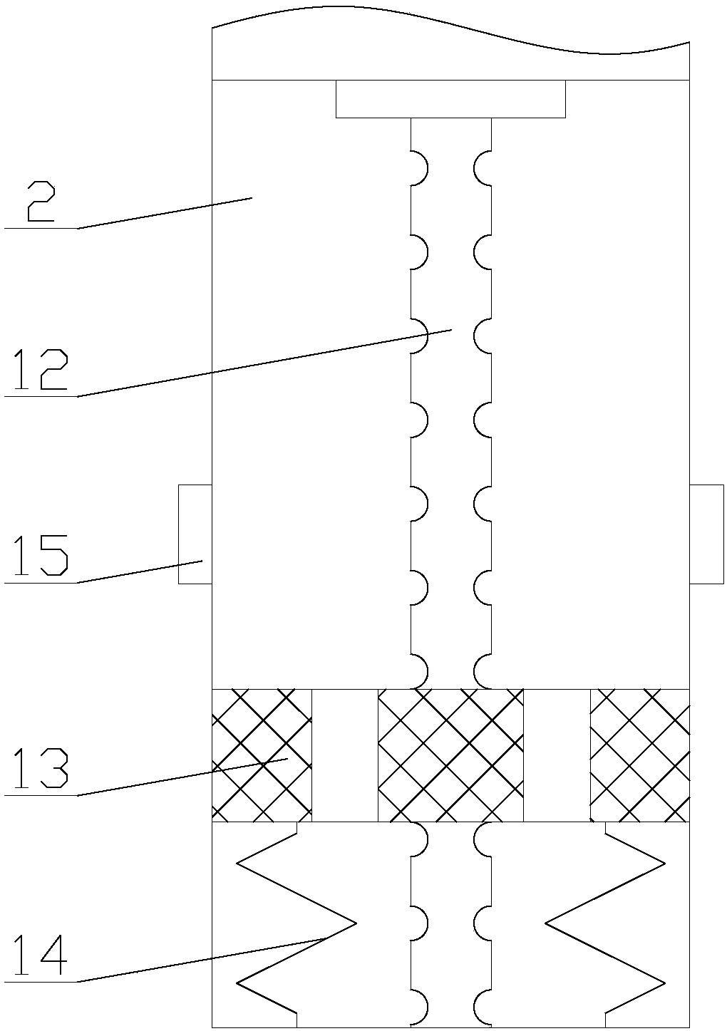
[0028] Such as figure 1 As shown, a safe and reliable damping system for new energy vehicles includes an outer tube 1, a shaft center 2, a piston 3 and a return spring 4, and also includes a flow distribution mechanism and a dust removal mechanism. The flow distribution mechanism is arranged on the outer pipe 1 Inside, the dust removal mechanism is arranged above the outer pipe 1;

[0029] Through the diversion mechanism, when the instantaneous pressure of the hydraulic oil is too high, it can divert the hydraulic oil, and consume the energy generated by the vibration of the car through various actions, preventing all the high-pressure hydraulic oil from acting...


PUM


Abstract

The invention relates to a safe and reliable shock mitigation system for a new-energy automobile. The safe and reliable shock mitigation system comprises an outer pipe, an axis, a piston, a reset spring, a flow dividing mechanism and a dust removing mechanism; the flow dividing mechanism comprises a control component and a moving component; the control component comprises two rotating units; the moving component comprises a fixing rod, a moving block, a second spring, an oil outlet and a telescopic unit; and the dust removing mechanism comprises a driving chamber, a driving motor, a driving wheel, a connecting rod, a loop ring, a cylinder and a sweeping brush. According to the safe and reliable shock mitigation system for the new-energy automobile, the flow of hydraulic oil can be dividedby virtue of the flow dividing mechanism so that an oil hole can be prevented from being damaged by high pressure which cannot be borne by the oil hole, and the safety and the reliability of a hydraulic shock absorber are greatly improved; by virtue of the dust removing mechanism, dust and impurities are prevented from entering the hydraulic shock absorber along with the axis so that blocking of the oil hole is prevented, the service life of the hydraulic shock absorber is not affected, and the practicability and the reliability of the hydraulic shock absorber are improved.

Description

technical field [0001] The invention relates to the field of shock absorbing systems for new energy vehicles, in particular to a safe and reliable shock absorbing system for new energy vehicles. Background technique [0002] New energy vehicles refer to vehicles that use unconventional vehicle fuels as power sources, integrate advanced technologies in vehicle power control and drive, and form vehicles with advanced technical principles, new technologies, and new structures. Hydraulic shock absorbers are new One of the key components of energy vehicles, it is mainly used to buffer the impact force transmitted from the uneven road to the frame or body, and attenuate the vibration caused by it, so as to ensure the smooth driving of the car, improve the ride feeling, and increase the performance of new energy vehicles. Stability, comfort and safety. [0003] But the existing hydraulic shock absorber still has some deficiencies in the process of actual use. For example, the work...

Claims


Application Information

Patent Timeline
IPC IPC(8): F16F15/04F16F15/023F16F9/32B08B1/02
CPCB08B1/02F16F9/3207F16F15/023F16F15/04
Inventor 蒙泽喜
Owner HUNAN KANGDEJIA FORESTRY TECH CO LTD
Why Eureka
Try Eureka