
Three-axis stable follow-up tracking device of shipborne satellite antenna

A satellite antenna, three-axis stabilization technology, applied to antennas, antennas suitable for movable objects, electrical components, etc., can solve problems such as unfavorable civilian market application promotion, high cost, complex structure, etc.

Inactive Publication Date: 2013-06-05
NINGBO SENFU MACHINERY & ELECTRIC MFG
View PDF5 Cites 32 Cited by
  • Summary
  • Abstract
  • Description
  • Claims
  • Application Information

AI Technical Summary

Problems solved by technology

[0002] Different from the ground satellite antenna, when the ship-borne satellite antenna is tracking and aiming at the target geosynchronous communication satellite, in addition to overcoming the interference of strong wind and air flow, it also needs to automatically control the parabolic satellite antenna to aim at The target communication satellite performs follow-up tracking of roll, pitch, and azimuth rotation. The existing technology uses an inertial gyro stabilization system on a three-axis antenna base to control the parabolic satellite antenna to align with the target satellite for follow-up tracking. For example, China Patent "Three-axis Shipborne Antenna Gyro Stabilization Device" 92231278.8; Due to the complex structure and high cost of the gyro system, which is not conducive to the application and promotion of the civilian market, the existing technology has the problems and shortcomings of complex structure, high cost, and difficulty in civilian use

Method used


Image

  • Three-axis stable follow-up tracking device of shipborne satellite antenna

Examples


Embodiment Construction

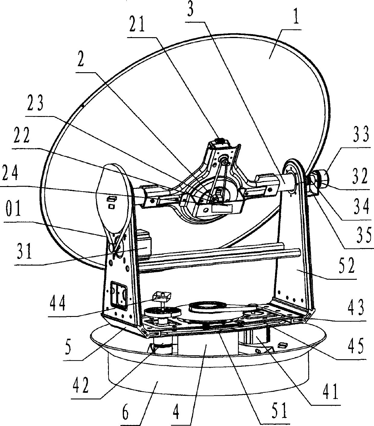
[0022] refer to figure 1 , a three-axis stable follow-up tracking device for a shipborne satellite antenna of the present invention, comprising a parabolic antenna 1, a roll rotating shaft 2, a pitch rotating shaft 3, an azimuth rotating shaft 4, a bracket 5, and a base 6, wherein: the parabolic dish The antenna 1 is a parabolic thin-walled aluminum alloy component; the focal point of the parabolic antenna 1 is provided with a satellite signal receiving head;

[0023] The roll shaft 2 is a shaft mechanism that carries the parabolic antenna 1 and rolls on the pitch shaft 3;

[0024] The pitch rotating shaft 3 is a rotating shaft mechanism that carries the rolling rotating shaft 2 and performs pitching rotation on the support 5;

[0025] The azimuth rotating shaft 4 is a rotating shaft mechanism for carrying the bracket 5 to perform azimuth rotation on the base 6;

[0026] The support 5 is composed of a crossbeam 51 and a stand 52, and is a steel member in the shape of a recta...


PUM


Abstract

The invention discloses a three-axis stable follow-up tracking device of a shipborne satellite antenna. The three-axis stable follow-up tracking device of the shipborne satellite antenna comprises a parabolic antenna (1), a roll rotary shaft (2), a pitching rotary shaft (3), as azimuth rotary shaft (4), a support (5) and a base seat (6). Due to the adoption of a three-axis rotation device formed by the components and the technical scheme including that the azimuth rotary shaft is fixedly connected in the center of the bottom of the base seat in a vertically upward mode, the center of a cross beam of the support is rotationally connected at the upper end of the azimuth rotary shaft, the pitching rotary shaft is rotationally and horizontally arranged on the upper portions of two stand supports of the support, the roll rotary shaft is located above the center position of the pitching rotary shaft and in rotational orthogonality connection with the pitching rotary shaft, the parabolic antenna is fixedly connected on the roll rotary shaft, and a feedback system composed of a photoelectric sensor, a position potentiometer, an angular velocity sensor, an electronic compass, a rotary encoder and a global position system (GPS) receiver is adopted to replace a gyro system, the shipborne satellite antenna is enabled to achieve the purposes of being simplified in structure, lowered in cost, and easy to civilianize.

Description

technical field [0001] The invention relates to a follow-up tracking device for carrying and controlling a satellite antenna, specifically, it is used to carry and control a ship-borne satellite antenna installed on a ship, and automatically track and aim at the earth as the ship's course changes and the ship's hull fluctuates. A three-axis stable follow-up tracking device for a ship-borne satellite antenna for synchronous communication satellites to receive satellite information. Background technique [0002] Different from the ground satellite antenna, when the ship-borne satellite antenna is tracking and aiming at the target geosynchronous communication satellite, in addition to overcoming the interference of strong wind and air flow, it also needs to automatically control the parabolic satellite antenna to aim at The target communication satellite performs follow-up tracking of roll, pitch, and azimuth rotation. The existing technology uses an inertial gyro stabilization...

Claims


Application Information

Patent Timeline
Patent Type & Authority Applications(China)
IPC IPC(8): H01Q3/02H01Q1/34H01Q19/12
Inventor 金宗宝葛超峰尤军达尤思光潘万松尤海平任永刚陈绍荣
Owner NINGBO SENFU MACHINERY & ELECTRIC MFG
Learn More