phase locked loop

A technology of phase-locked loop and frequency and phase detector, which is applied in the field of phase-locked loop circuit design, can solve the problems of control voltage Vctrl fluctuations and influence on the stability of the phase-locked loop, and achieve frequency stability and loop stability Effect

Active Publication Date: 2016-01-06
SEMICON MFG INT (SHANGHAI) CORP
View PDF4 Cites 0 Cited by
  • Summary
  • Abstract
  • Description
  • Claims
  • Application Information

AI Technical Summary

Problems solved by technology

[0010] When the phase-locked loop is locked, ideally, the frequency and phase of the reference clock Fref and the feedback signal Ffb are consistent, but in practical applications, when the phase-locked loop is locked, the frequencies of the feedback signal Ffb and the reference clock Fref are equal , the phase difference is a small constant value, which will cause fluctuations in the control voltage Vctrl, causing the output signal Fout to generate unwanted spurs, which will affect the stability of the phase-locked loop

Method used


Image

  • phase locked loop
  • phase locked loop
  • phase locked loop

Examples


Embodiment Construction

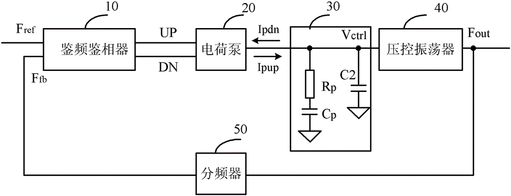
[0032] When the phase-locked loop is locked, ideally, the frequency and phase of the reference clock Fref and the feedback signal Ffb are consistent, but in practical applications, due to the characteristics of the device in the Influenced by factors such as mismatch and leakage current, when the PLL is locked, the frequencies of the feedback signal Ffb and the reference clock Fref are equal, and the phase difference is a small constant value, generally less than 0.5 nanoseconds. Fluctuations in the control voltage Vctrl may be caused, causing unwanted spurs in the output signal Fout.

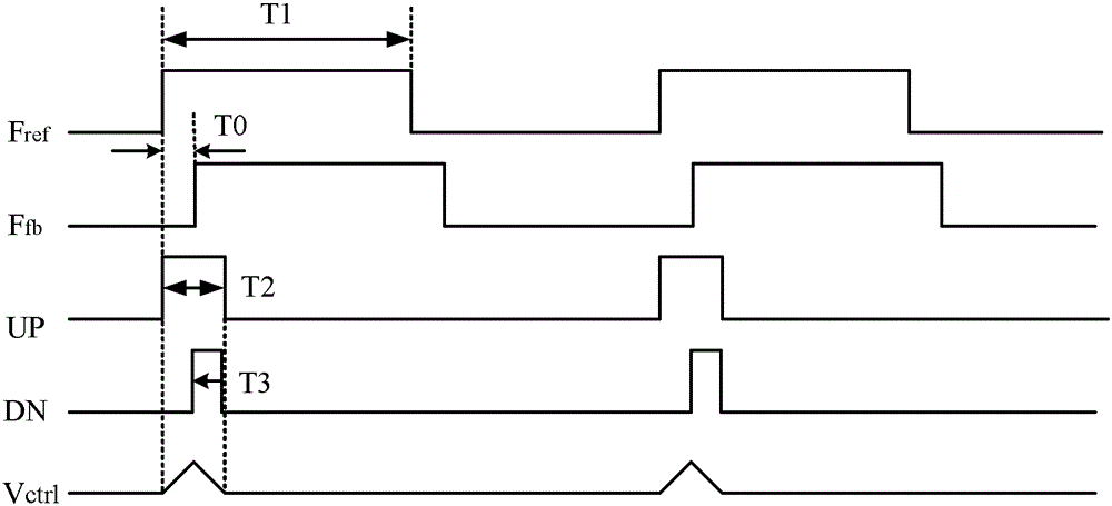
[0033] Please refer to figure 2 , figure 2 for figure 1 The shown schematic diagram of the pulse signal of the phase locked loop circuit in the locked state, including: an active high input signal Fref, a feedback signal Ffb, a pulse control signal UP, a pulse control signal DN and a control voltage output by the low-pass filter 30 Vctrl, the frequency of the output signal Fout is the same...


PUM


Abstract

A PLL comprises a phase frequency detector (PFD), a charge pump, a low pass filter, a voltage-controlled oscillator, a frequency divider, and a switch capacitor cell, wherein the switch capacitor cell comprises a switch and a first capacitor, the switch is provided with a first end, a second end and a control end, the first end of the switch is connected with an output end of the charge pump, the second end of the switch is connected with the low pass filter, one end of the first capacitor is connected with the first end of the switch, the other end of the first capacitor is grounded, and switch control signals are input in the control end of the switch. After the PLL is locked, the switch is disconnected when charging and discharging currents charge and discharge the low pass filter and connected after the charging and discharging. The stability of the PLL is improved.

Description

technical field [0001] The invention relates to a phase-locked loop circuit design technology, in particular to a phase-locked loop. Background technique [0002] With the development of contemporary microelectronics technology, the main frequency and performance of microprocessors and workstation systems have been improved, and higher and higher requirements have been placed on the design of the clock generation circuit of the system. As a common design technique, a phase-locked loop (PLL, PhaseLockedLoop) is widely used in a system-on-chip (SOC, SystemonChip) to form a clock generation circuit. [0003] like figure 1 As shown, the phase-locked loop circuit generally includes a frequency discriminator 10 , a charge pump 20 , a low-pass filter 30 , a voltage-controlled oscillator 40 and a frequency divider 50 . The frequency discriminator 10 is used to detect the frequency difference and phase difference between the input signal Fref and the feedback signal Ffb, and genera...

Claims


Application Information

Patent Timeline
Patent Type & Authority Patents(China)
IPC IPC(8): H03L7/087H03L7/099
Inventor 符志岗
Owner SEMICON MFG INT (SHANGHAI) CORP
Why Eureka
Try Eureka