
Automatic tracking shooting device

A camera device and automatic tracking technology, applied in image communication, television, signal transmission system, etc., can solve the problems of infrared signal being blocked, time-consuming, poor picture effect, etc.

Inactive Publication Date: 2013-06-05
上海迈辉信息技术有限公司
View PDF0 Cites 4 Cited by
  • Summary
  • Abstract
  • Description
  • Claims
  • Application Information

AI Technical Summary

Problems solved by technology

However, in practical applications, it is found that this camera method does not work well
It is mainly reflected in the following two aspects: On the one hand, since the infrared signal is transmitted in a straight line, if an obstacle is encountered in the middle, the system will fail. For example, when the teacher turns his back to write on the blackboard, the infrared signal may be blocked , resulting in system failure; on the other hand, it takes time to start the camera pan / tilt. Real-time tracking and shooting will cause the camera to start frequently. If the teacher walks around frequently, it is difficult for the camera pan / tilt to start so quickly resulting in poor picture quality

Method used


Image

  • Automatic tracking shooting device
  • Automatic tracking shooting device
  • Automatic tracking shooting device

Examples


specific Embodiment

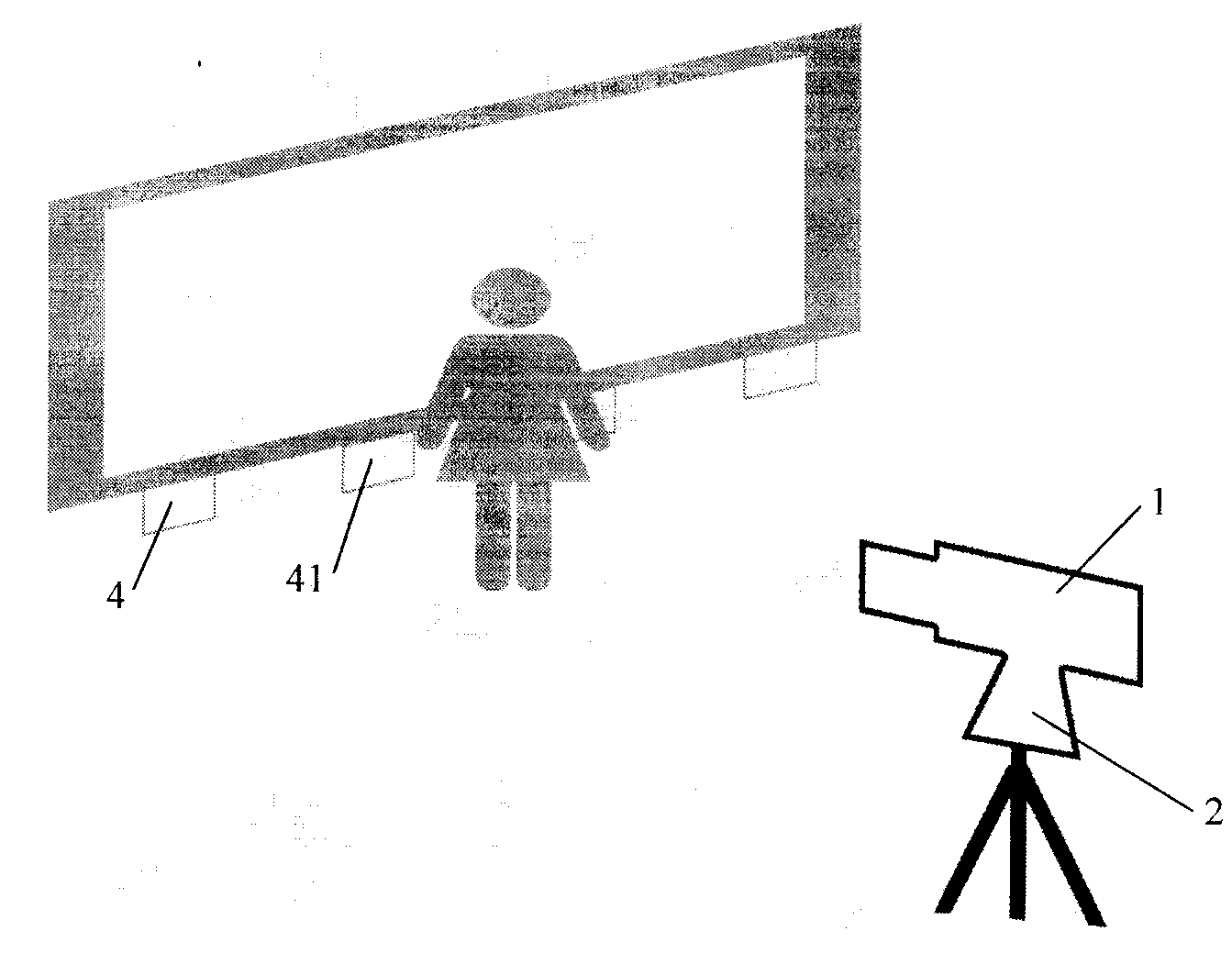
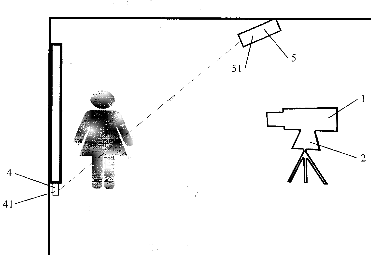
[0020] In this embodiment, the first and second infrared signal emitter groups 4 , 5 each include four infrared signal emitters 41 , 51 .

[0021] The four infrared signal emitters 41 of the first infrared signal emitter group 4 are uniformly distributed and fixed below the blackboard along the blackboard lateral direction, and the four infrared signal emitters 51 of the second infrared signal emitter group 5 are fixed on the upper front of the blackboard. On the ceiling, and the positions of the four infrared signal transmitters 51 of the second infrared signal transmitter group 5 correspond to the positions of the four infrared signal transmitters 41 of the first infrared signal transmitter group 4 . At this time, every two pairs of adjacent infrared signal transmitters 41, 51 form a facing inclined plane, that is, the front of the blackboard is evenly divided into three inclined planes.

[0022] Start the automatic tracking camera device of the present invention to start sh...


PUM


Abstract

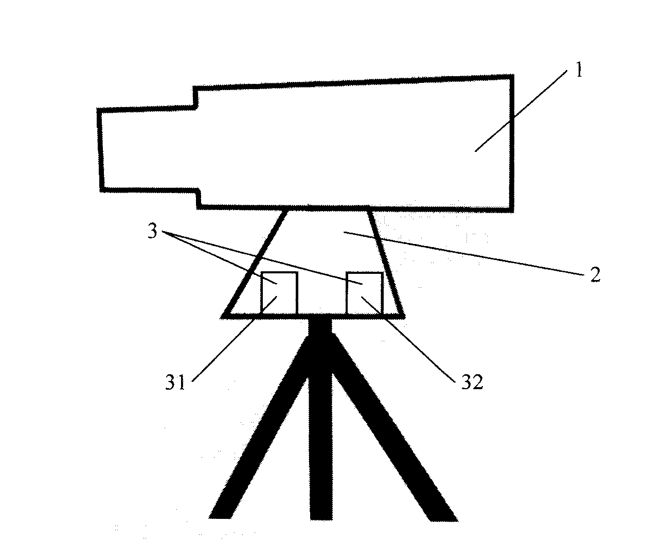
The invention relates to a shooting device. An automatic tracking shooting device comprises a camera and a camera holder, wherein the camera is installed in front of a black board and is arranged on the camera holder. The automatic tracking shooting device further comprises a master control processing chip and two infrared signal emitter groups, each infrared signal emitter group comprises a plurality of infrared signal emitters, the master control processing chip is installed inside the camera holder, the first infrared signal emitter group is transversely fixed below the black board along the black board, the second infrared signal emitter group is fixed on a ceiling in front of and above the black board, and the infrared signal emitters in the second infrared signal emitter group correspond to the infrared signal emitters in the first infrared signal emitter group one to one in position. The automatic tracking shooting device changes installation positions of the infrared signal emitters, lowers the starting frequency of the camera holder, and therefore enables shot images to be smooth.

Description

technical field [0001] The present invention relates to imaging devices. Background technique [0002] At present, in the case of relatively scarce educational resources, distance education and quality courses have become a fashionable solution. However, due to insufficient network bandwidth and other reasons, distance teaching is still difficult to popularize on a large scale. Relatively speaking, the recording of high-quality courses has become the mainstream solution. The recording of excellent courses must have a good effect. In addition to the relatively high requirements for the clarity of the recording screen, the automatic tracking of the teacher by the camera is also an indispensable function to make the screen look more humane. [0003] At present, the camera method of the excellent courses is mainly the real-time wireless docking tracking camera method. The camera method is to let the teacher wear an infrared signal emitting device, detect and locate the infrare...

Claims


Application Information

Patent Timeline
Patent Type & Authority Applications(China)
IPC IPC(8): H04N5/225G08C23/04
Inventor 杨永玲陈善军施凯
Owner 上海迈辉信息技术有限公司
Learn More