Brake system having a connection, which can be switched by means of a brake pedal, for decoupling a drive device from a piston-cylinder unit

A technology of braking equipment and driving devices, applied in the direction of braking action starting devices, braking transmission devices, hydraulic braking transmission devices, etc., can solve the problems of mechanical structure and manufacturing costs of clutches or connecting parts, and achieve improved diagnosis and feasibility The effect of high reliability, low consumption and high fail-safety

Inactive Publication Date: 2013-06-05
IPGATE
View PDF7 Cites 5 Cited by
  • Summary
  • Abstract
  • Description
  • Claims
  • Application Information

AI Technical Summary

Problems solved by technology

Such clutches or couplings are extremely compl...

Method used


Image

  • Brake system having a connection, which can be switched by means of a brake pedal, for decoupling a drive device from a piston-cylinder unit
  • Brake system having a connection, which can be switched by means of a brake pedal, for decoupling a drive device from a piston-cylinder unit
  • Brake system having a connection, which can be switched by means of a brake pedal, for decoupling a drive device from a piston-cylinder unit

Examples


Embodiment Construction

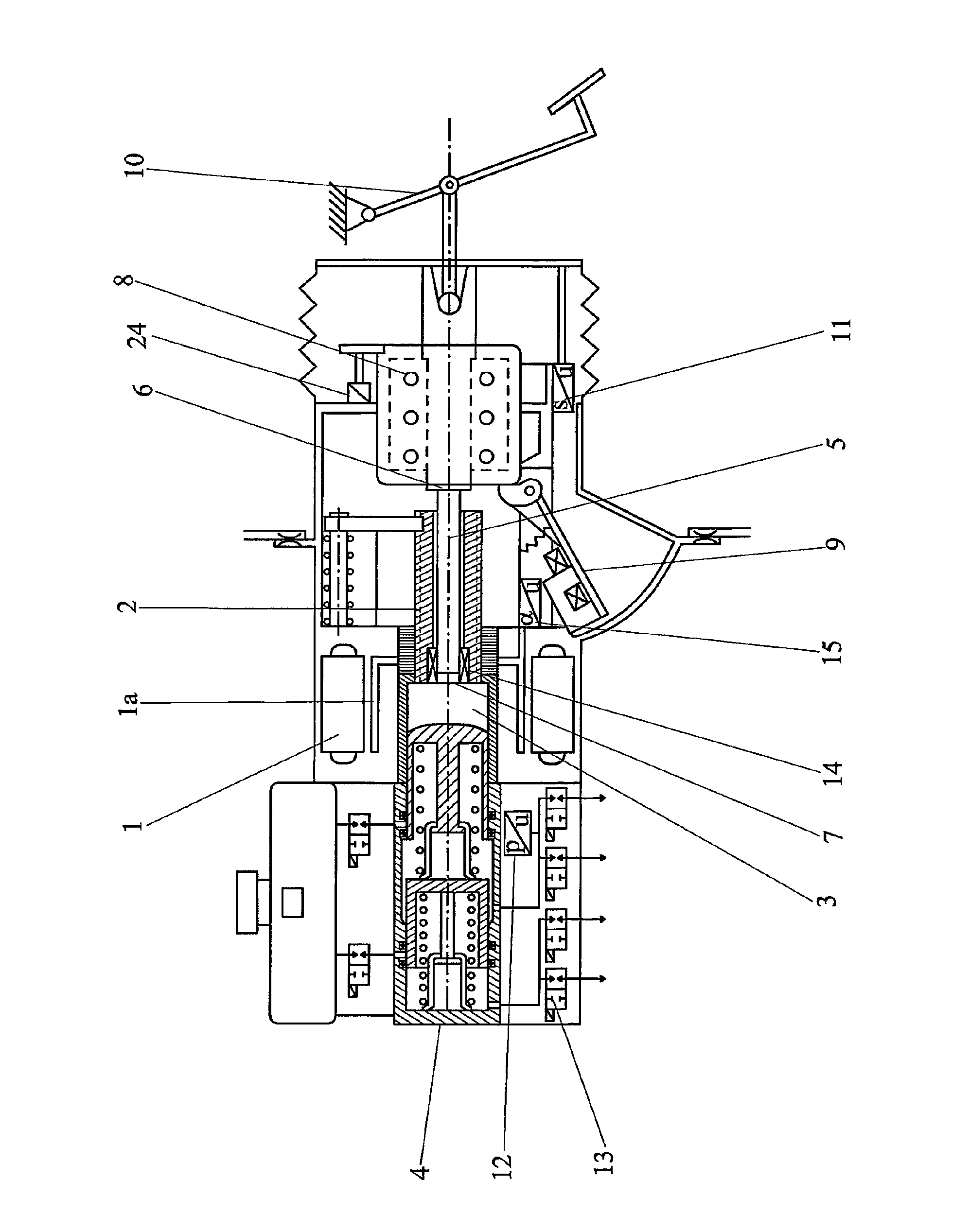
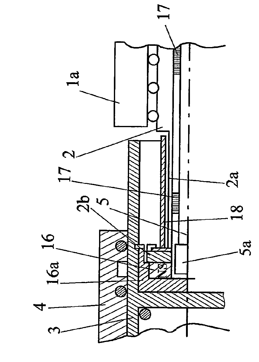
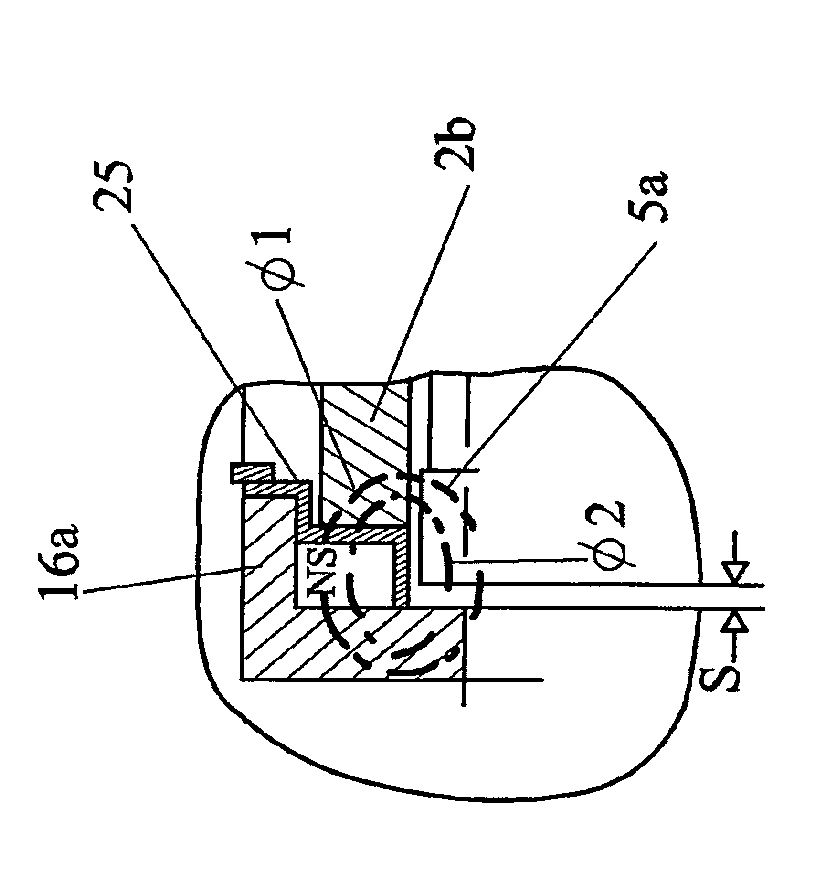
[0029] figure 1 An integrated brake booster with an electric motor 1 , which drives a screw 2 , with a corresponding rotor 1 a and a screw nut is shown. The pushrod piston 3 is movably arranged in the tandem master cylinder 4 . Furthermore, the clutch 14 acts between the push rod piston 3 and the screw 2 only when the electric motor 1 or the drive is functioning properly. The clutch 14 itself and the connection between the push rod piston 3, the screw rod 2 and the pedal push rod 5 that is disconnected or disconnects the clutch 14 in the event of a failure figure 1 is shown only schematically, and by means of Figures 2 to 4 Elaborate.

[0030] In normal operation, actuation of the brake pedal 10 is detected via the pedal travel sensor 11 and the pushrod piston 3 is actuated via the electric motor 1 and the screw 5 moved by the rotor of said electric motor for pressure buildup and pressure drop. The function of pressure build-up and pressure drop is already sufficiently kn...


PUM


Abstract

The invention relates to a brake system having at least one piston-cylinder unit (4) for generating a pressure in at least one working chamber, wherein the working chamber is connected via at least one hydraulic line to at least one wheel brake, and wherein the brake system furthermore has at least one drive device (1) and one actuating device (10), in particular in the form of a brake pedal, and, in normal operation, the drive device (1, 1a) acts via a first force-transmitting means (2) on the at least one first piston (3) of the piston-cylinder unit (4) for the build-up and dissipation of pressure, and in the event of a fault, the actuating device (10) acts mechanically via a second force-transmitting means (5, 16) on the piston (3), wherein the adjustment of the second force-transmitting means (5, 16) by means of the actuating device (10); separates the connection between the first force-transmitting means (2) and the piston (3).

Description

technical field [0001] The invention relates to a brake system having at least one piston-cylinder unit for generating pressure in at least one working chamber, wherein the working chamber is connected to at least one wheel brake via at least one hydraulic line, and wherein the brake system additionally having at least one drive and an actuating device, in particular in the form of a brake pedal, and the drive acts in normal operation on the first piston of the piston-cylinder unit by means of a first force transmission mechanism for pressure build-up and pressure drop , and in the event of a fault, the actuating device acts mechanically on the piston via the second force transmission. Background technique [0002] The trend in braking systems is to replace the vacuum brake booster (V-BKV) by a hydraulic or electric brake booster (BKV). An embodiment of an electric BKV is described in DE 10 2004 050 103 A1. Here, pressure regulation takes place in separate groups. The ele...

Claims


Application Information

Patent Timeline
IPC IPC(8): B60T13/74
CPCB60T7/042B60T13/745B60T8/4077B60T11/18
Inventor 海因茨·莱贝尔瓦伦丁·翁特尔弗罗纳克里斯蒂安·克格尔施佩格
Owner IPGATE
Why Eureka
Try Eureka