
Press-mounting, locking and balancing device for blanking cap and press-mounting machine for blanking cap

A technology of balancing devices and blocking caps, which is applied in metal processing, metal processing equipment, manufacturing tools, etc., can solve problems such as difficult implementation, complicated equipment, and inability to achieve absolute synchronization in the press-fitting process, and achieve good versatility and structure simple effect

Active Publication Date: 2013-06-12
ANHUI JIANGHUAI AUTOMOBILE GRP CORP LTD
View PDF7 Cites 8 Cited by
  • Summary
  • Abstract
  • Description
  • Claims
  • Application Information

AI Technical Summary

Problems solved by technology

However, the prerequisite for the balance of the press-fitting force when both sides are press-fitted at the same time is that the process holes on both sides of the cylinder block are arranged symmetrically and coaxially. The axes coincide, which is difficult to achieve in actual production, and the press-fitting process cannot be absolutely synchronized
Under the condition that the number of process holes on both sides of the cylinder block is asymmetrical, in order to achieve the balance of the press-fitting force, the invention fixes the ejector rod on the cantilever on the side with a small number (equivalent to setting up the support cylinder), which still cannot be completely solved. The equipment complexity problem of press-fitting force balance

Method used


Image

  • Press-mounting, locking and balancing device for blanking cap and press-mounting machine for blanking cap
  • Press-mounting, locking and balancing device for blanking cap and press-mounting machine for blanking cap
  • Press-mounting, locking and balancing device for blanking cap and press-mounting machine for blanking cap

Examples


Embodiment Construction

[0036] In the following description of the embodiments of the present invention in conjunction with the accompanying drawings, it is defined that the positive direction of the Z-axis is up, the positive direction of the X-axis is right, and the positive direction of the Y-axis is front.

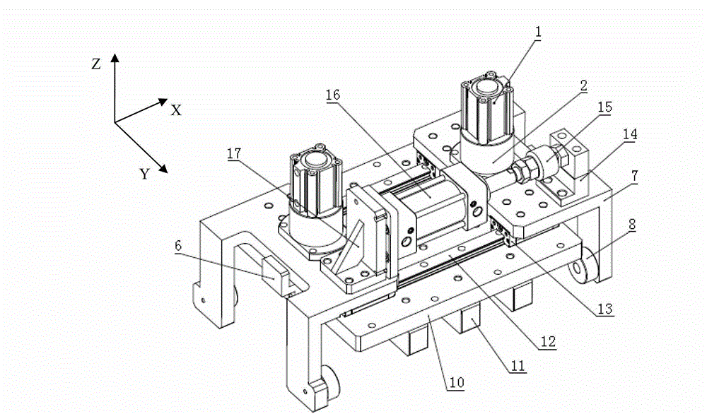
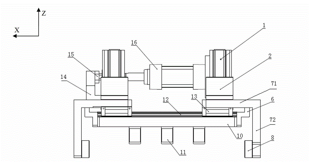
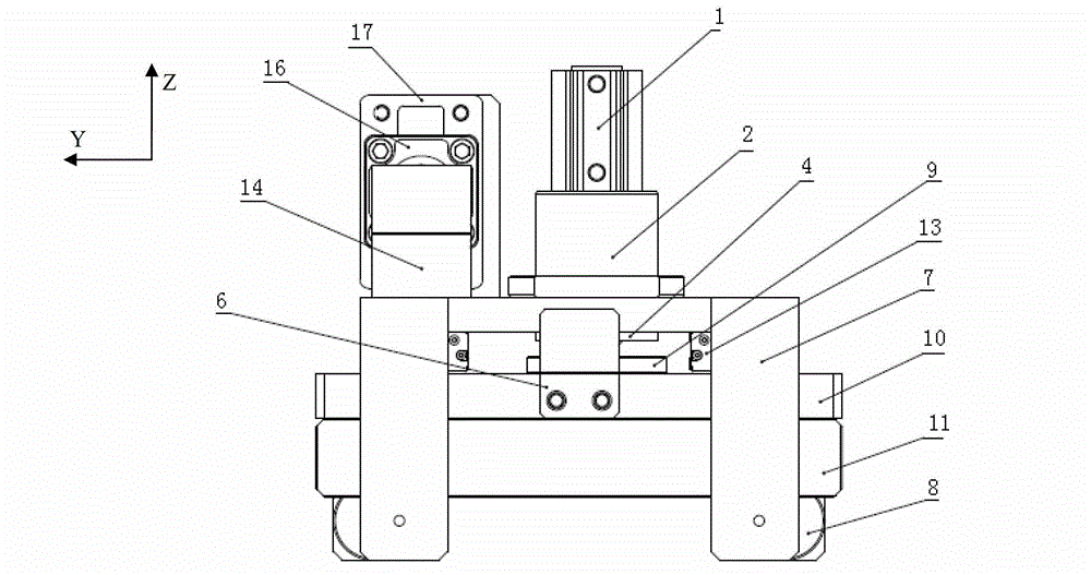
[0037] combine figure 1 , figure 2 , image 3 and Figure 4 . The bottom plate 10 is the connection supporting mechanism of the whole device. A strip-shaped stopper 11 is installed below the bottom plate 10 . Two slide rails 12 are installed above the bottom plate 10 . The clamping frame 7 is divided into two parts, one part is the horizontal part 71 of the clamping frame on which the slider 13 is installed underneath, and the other part extends from the edge of the horizontal part 71 of the clamping frame toward the bottom of the bottom plate (ie, the negative direction of the Z axis). There are two clip arms 72, and the two clip arms 72 are spaced apart from each other. On the left ...


PUM


Abstract

The invention provides a press-mounting, locking and balancing device for a blanking cap and a press-mounting machine for the blanking cap. The press-mounting, locking and balancing device for the blanking cap comprises a baseplate, a stop block mounted below the baseplate, a pair of clamping frames mounted above the baseplate and being in sliding fit with the baseplate, an X-direction driving mechanism used for driving the pair of clamping frames, tubular fixed columns mounted above the clamping frames, limit pins in sliding fit with the fixed columns in a Z direction, Z-direction driving mechanisms mounted on the fixed columns and used for driving the limit pins, and stop collars mounted on the baseplate, wherein each clamping frame is provided with spaced clamping arms; through holes communicated with the inner chambers of the fixed columns are formed in the clamping frames; and when the X-direction driving mechanism drives the pair of clamping frames to slide in opposite directions to reach the working position, the inner chambers of the stop collars are communicated with the inner chambers of the fixed columns and the through holes. According to the invention, the mechanism design is simplified and the universality is enhanced.

Description

technical field [0001] The invention relates to the field of fixtures, in particular to a locking balance device used for a cap pressing machine and a cap pressing machine using the device. Background technique [0002] Process holes such as water holes, oil holes, and sand cleaning holes are provided on the engine cylinder block and cylinder head. These process holes need to be glued and pressed to seal the plugging caps. At present, the plug is generally pressed by a plug press machine, such as the machine tool disclosed in the Chinese utility model patent with the application number 201120417586.3 and the name "engine cylinder bowl plug servo gluing press-fitting machine tool". During the pressing process of the plugging machine, the pressure head of the plugging cap is generally driven by hydraulic pressure, and the pressing force is relatively large. Therefore, it is necessary to set a support cylinder on the opposite side of the pressing part to balance the pressing fo...

Claims


Application Information

Patent Timeline
IPC IPC(8): B23P19/027
Inventor 黄浩谢飞李路路曹金贵何华
Owner ANHUI JIANGHUAI AUTOMOBILE GRP CORP LTD
Learn More