Step-by-step tightening-type template limiting fastener

A technology of step-by-step tightening and formwork, which is applied to the joints of formwork/formwork/work frame, the preparation of building components on site, and construction, which can solve the problems of easy loss and easy fall of step-by-step tightening devices, so as to prevent Drop and lose, solve the effect of easy falling, and facilitate centralized collection and storage

Inactive Publication Date: 2013-06-12
朱新伟
View PDF8 Cites 2 Cited by
  • Summary
  • Abstract
  • Description
  • Claims
  • Application Information

AI Technical Summary

Problems solved by technology

[0006] The purpose of the present invention is to provide a step-by-step tightening formwork limit

Method used


Image

  • Step-by-step tightening-type template limiting fastener
  • Step-by-step tightening-type template limiting fastener
  • Step-by-step tightening-type template limiting fastener

Examples


Embodiment Construction

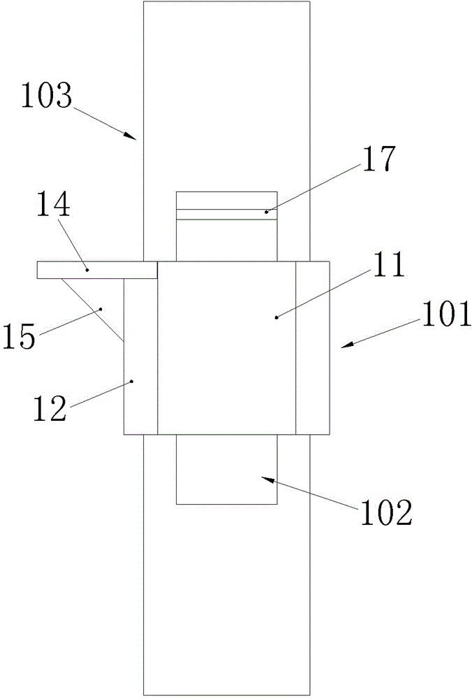
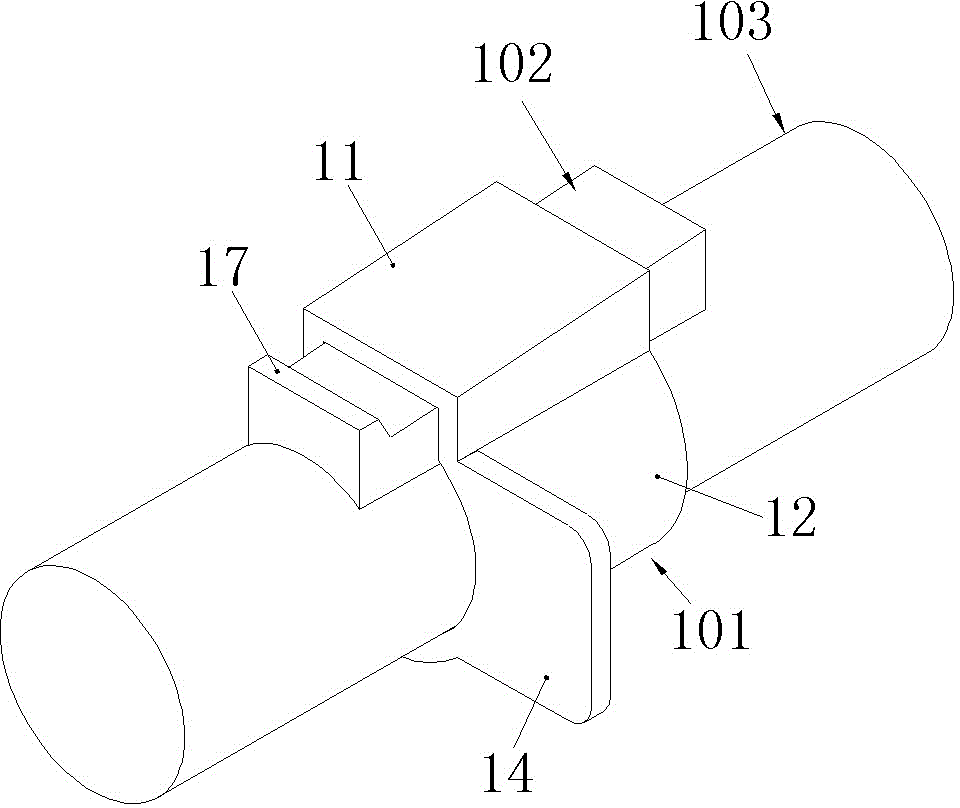
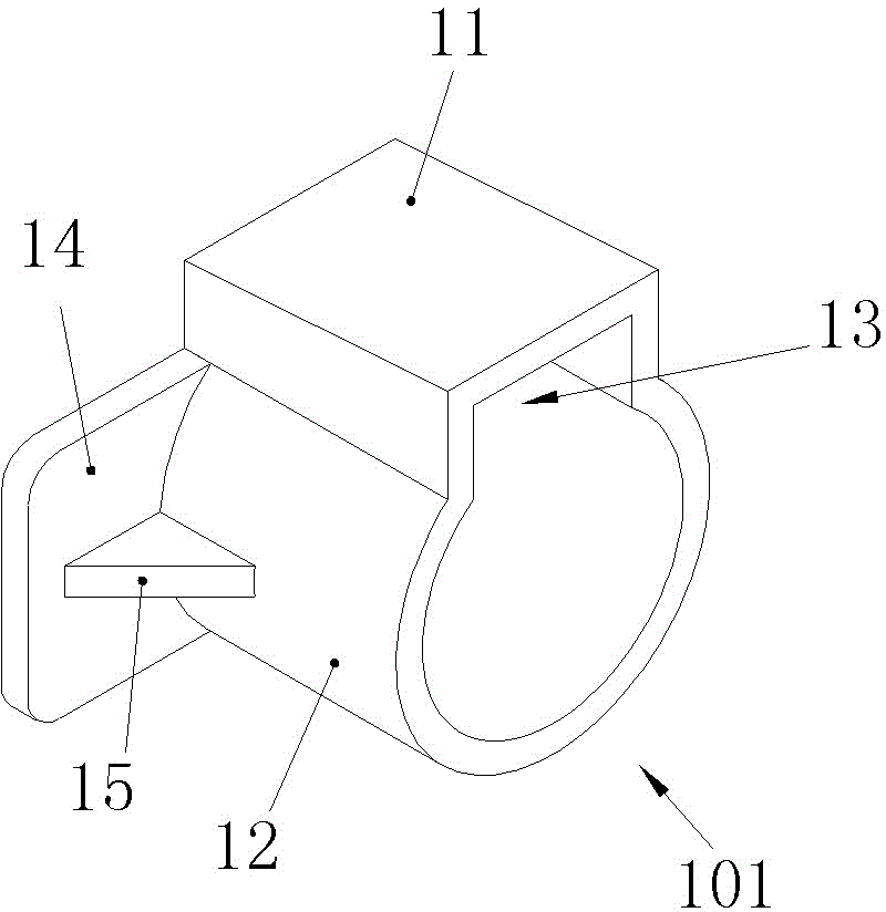
[0025] Examples of step-by-step formwork limit fasteners, such as Figure 1-6 As shown, the limit fastener in this embodiment is composed of a support sleeve 101 and an expansion block 102 . The support sleeve 101 includes a locking part 11 and a sliding sleeve part 12, wherein the cross section of the sliding sleeve part 12 is C-shaped, and the cross-section of the locking part 11 is U-shaped, and the locking part 11 and the sliding sleeve part 12 are arranged mouth to mouth. The U-shaped groove surrounded by the locking part 11 is a through groove through up and down, and the through groove forms a lock groove 13. The groove bottom surface of the lock groove 13 is a slope that gradually inclines toward the inner side of the support sleeve from back to front; in addition, the sliding sleeve The front end of the part 12 is provided with a side wing 14 for pressing the corresponding formwork forward, and the side wing 14 protrudes toward the radial periphery of the support slee...


PUM


Abstract

The invention relates to the field of a building fastener, in particular to a step-by-step tightening-type template limiting fastener. The limiting fastener comprises a slide supporting sleeve which is sleeved on a scaffold steel pipe, wherein a locking groove which is sunken towards the radial periphery is arranged in the supporting sleeve, the locking groove is a through groove which runs from front to rear, the supporting sleeve is also provided with a side wing which is protruded towards the circumferential periphery and used for jacking a template, and the limiting fastener also comprises an expansion block which is tightly wedged in the locking groove and locks the supporting sleeve on the scaffold steel pipe. When the step-by-step tightening-type template limiting fastener is in use, the supporting sleeve can be sleeved on the corresponding scaffold steel pipe, so that the side wing is enabled to be contacted with the corresponding template through sliding, when the limiting fastener reaches a set position, the supporting sleeve is locked onto the steel pipe by knocking the expansion block, so that the template can be tightened and fixed; and since the supporting sleeve is directly sleeved on the scaffold steel pipe, the supporting sleeve is absolutely free from dropping off under the loosening situation and is free from being lost, and the problem that the existing step-by-step tightening device is easy to drop and lose can be solved.

Description

technical field [0001] The invention relates to the field of building fasteners, in particular to a step-by-step formwork limiting fastener. Background technique [0002] In the construction process of the building site, external molds are required for pouring concrete, so that the concrete can form the required shape after solidification in the formed pouring box. There is an evolution process in making the outer mold. Usually, the formwork is used to enclose the cavity of the required shape, and then the periphery of the formwork is clamped with a fastening device to ensure that it can withstand the impact of the vibrating device when the concrete is poured or the expansion force when the concrete is solidified. The initial fastening devices used metal nails, wedges, etc. (the initial templates were wooden boards), which were extremely inconvenient to assemble and disassemble. [0003] Up to now, the templates used in the construction industry have tended to be standardiz...

Claims


Application Information

Patent Timeline
IPC IPC(8): E04G17/04
Inventor 朱新伟
Owner 朱新伟
Why Eureka
Try Eureka